Turbomachine stator including a stage of stator vanes actuated by an automatically centered rotary ring

a technology of stator valves and stator tubes, which is applied in the direction of efficient propulsion technologies, machines/engines, liquid fuel engines, etc., can solve the problems of difficult to make shoes so as to enable the ring to be suitably coaxial with the casing, time-consuming, and heavy system weigh

Active Publication Date: 2011-05-10
SN DETUDE & DE CONSTR DE MOTEURS DAVIATION S N E C M A
View PDF9 Cites 19 Cited by
  • Summary
  • Abstract
  • Description
  • Claims
  • Application Information

AI Technical Summary

Benefits of technology

[0008]The invention provides a noticeable improvement in comparison with the above-mentioned prior art solutions, and, in operation, it enables the ring to be centered automatically while using a system that is relatively compact.
[0014]The structure in accordance with the invention makes it possible to obtain an actuator ring of low weight, and that is accurately centered (i.e. coaxial about the casing). In addition, assembly and adjustment of such a structure are simple and can be performed quickly. Finally, there is no need to provide operating clearance to accommodate expansion phenomena, thereby ensuring that the ring is properly centered regardless of the operating temperature, and in particular when cold.
[0015]The structure in accordance with the invention guarantees that the initial quality of centering is permanent, regardless of the operating temperature and regardless of the materials used for the ring and the casing. This improves control over the position of the actuator ring during all stages of control.
[0018]Compared with the system described in above-mentioned U.S. Pat. No. 4,130,375, it can be seen that the weight and the dimensions of the actuator ring are greatly reduced since the inner ring of the system described in that patent is omitted.

Problems solved by technology

The adjustments of the shoes enabling the ring to be made suitably coaxial with the casing are difficult to make and take time.
Such a system is heavy and bulky.

Method used


Image

  • Turbomachine stator including a stage of stator vanes actuated by an automatically centered rotary ring
  • Turbomachine stator including a stage of stator vanes actuated by an automatically centered rotary ring
  • Turbomachine stator including a stage of stator vanes actuated by an automatically centered rotary ring

Examples


Embodiment Construction

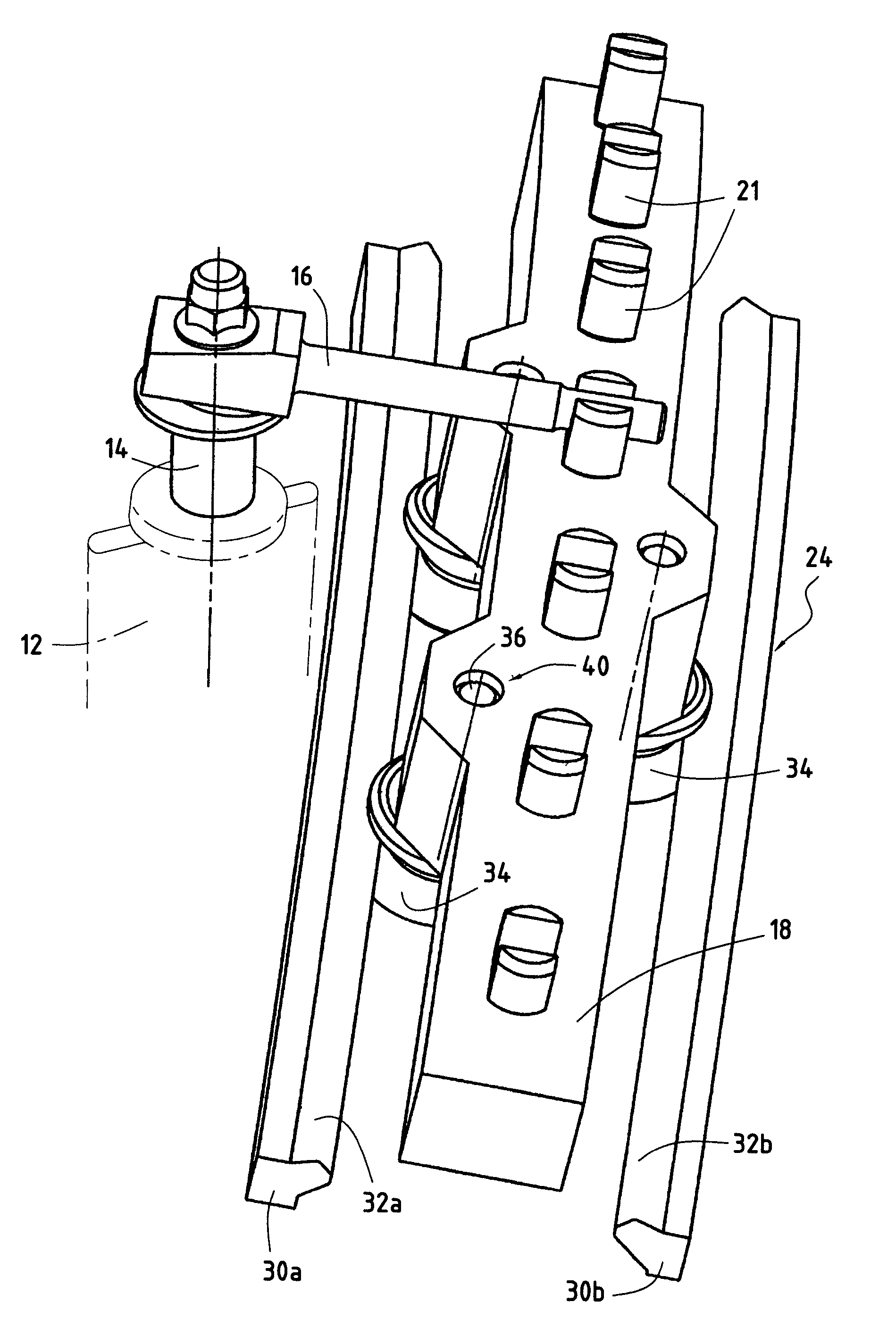
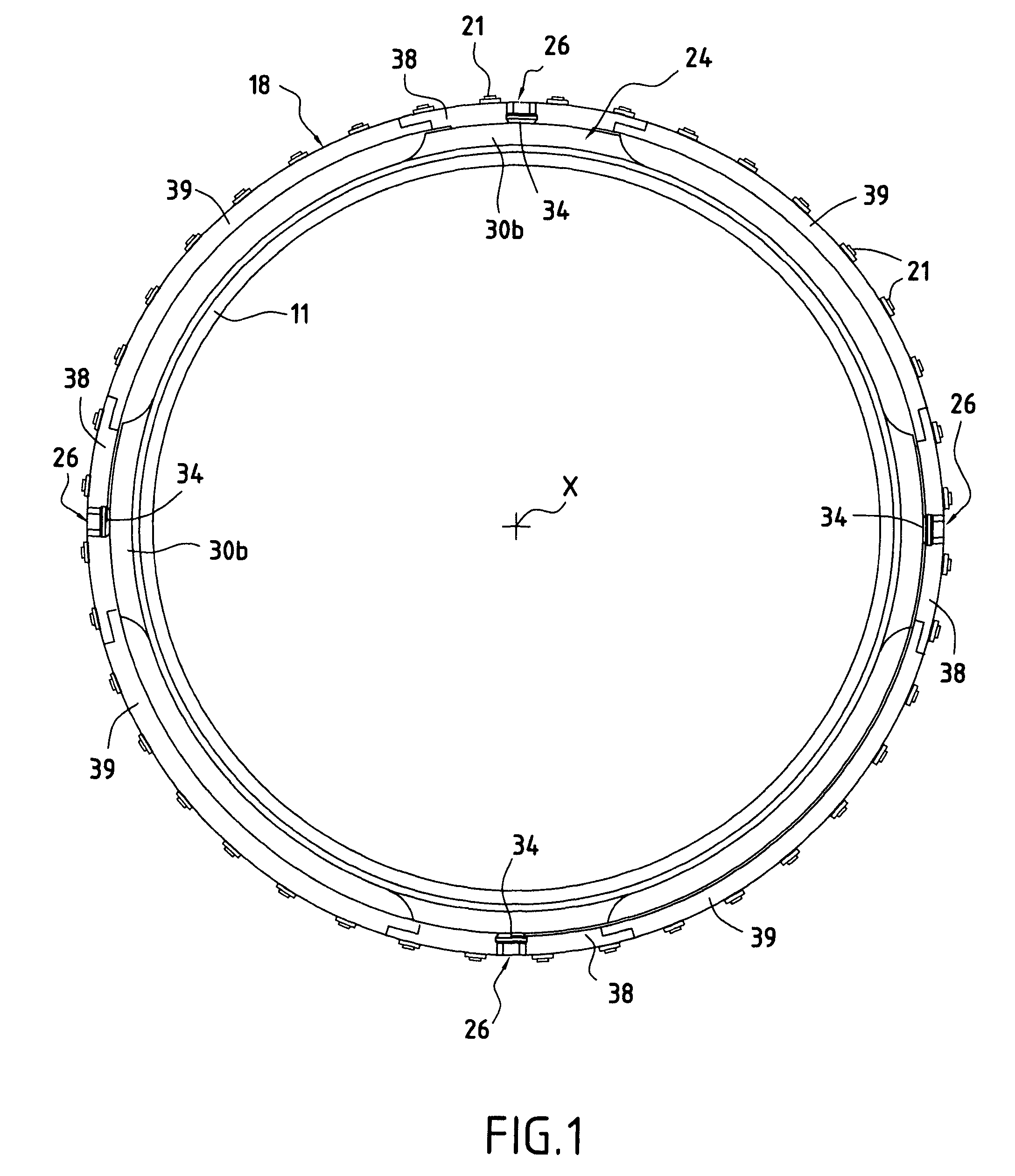
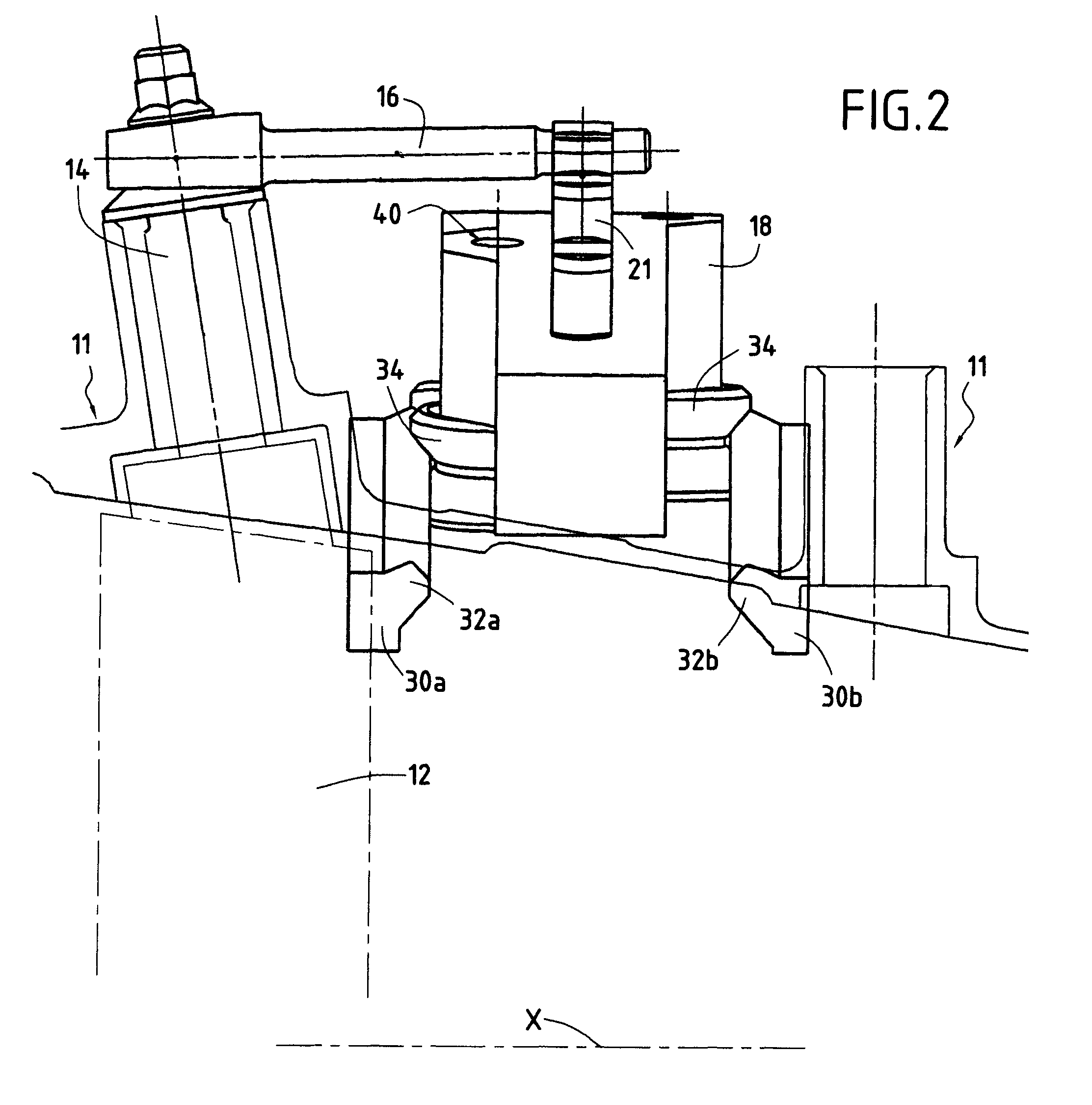
[0031]FIGS. 1 and 2 show a portion of a turbomachine casing 11 of axis X and housing variable pitch stator vanes 12. Each vane 12 has a pivot 14 projecting from the casing 11 and connected via a link 16 to an actuator ring 18 on the outside of the casing. On its outside surface, the ring 18 presents tenons 21 secured to the ends of the links 16. It can be understood that turning the actuator ring about the axis X causes the vanes 12 to pivot simultaneously through the same angle. In an airplane turbojet, the orientation of the vanes can be adjusted as a function of flying conditions.

[0032]The invention makes it possible to guarantee that the actuator ring 18 is centered, with said centering not being disturbed by differences in expansion between the casing 11 and the ring 18.

[0033]To do this, the casing 11 has on its outside a stationary coaxial annular rail 24, in this case formed integrally with the wall of the casing and projecting from its outside surface. At least three groups ...


PUM


Abstract

The stator includes a casing and at least one stage of variable-pitch stator vanes. The vanes are moved by an actuator ring outside the casing and are carried thereby. The ring is connected by links to the vanes in order to actuate them simultaneously. The casing includes a stationary coaxial rail projecting from the outside surface of the casing and at least three circumferentially spaced-apart groups of wheels are constrained to move along the rail. Each group of wheels is coupled to the ring by a radial guidance arrangement. Each group of wheels includes at least two wheels engaged with the rail, and each wheel being mounted to rotate on a radially-oriented pin, said pin being mounted directly on said ring.

Description

[0001]The invention relates to a turbomachine stator.[0002]The invention applies to terrestrial or aviation turbomachines, in particular to airplane turbojets, and more particularly to the compressors included in such turbomachines.BACKGROUND OF THE INVENTION[0003]More precisely, the invention relates to a turbomachine of the type comprising a stator having a casing and at least one stage of variable-pitch stator vanes, said vanes being moved by an actuator ring outside said casing and carried thereby, said ring being coupled by links to said vanes of said stage in order to actuate them simultaneously.[0004]In a turbomachine of this type, the stator of the compressor is fitted with at least one stage of stator vanes that are said to be of variable pitch since their position in the stream is adjustable. More precisely, the angle of attack of the vanes can be controlled as a function of the operating conditions of the turbomachine by a servo-control system that controls displacement o...

Claims


Application Information

Patent Timeline
Patent Type & Authority Patents(United States)
IPC IPC(8): F04D29/44
CPCF01D17/162F02C9/20F05D2260/50Y02T50/672Y02T50/60
Inventor BOURU, MICHEL ANDRE
Owner SN DETUDE & DE CONSTR DE MOTEURS DAVIATION S N E C M A
Why Eureka
Try Eureka