Eureka AIR delivers breakthrough ideas for toughest innovation challenges, trusted by R&D personnel around the world.

Crawler running gear

a running gear and crawler technology, applied in the field of crawler running gear, can solve the problems of difficult to produce precise bevels, time-consuming precise setting, and difficult to attach crawler supports to crossbeams

Inactive Publication Date: 2005-02-08
BAUER MASCH GMBH
View PDF10 Cites 19 Cited by
  • Summary
  • Abstract
  • Description
  • Claims
  • Application Information

AI Technical Summary

Benefits of technology

The object of the invention is to provide a simply constructed crawler running gear, where removable crawler supports can be installed in simple manner, but still in a precise way, even at a construction site, on the crossbeams.
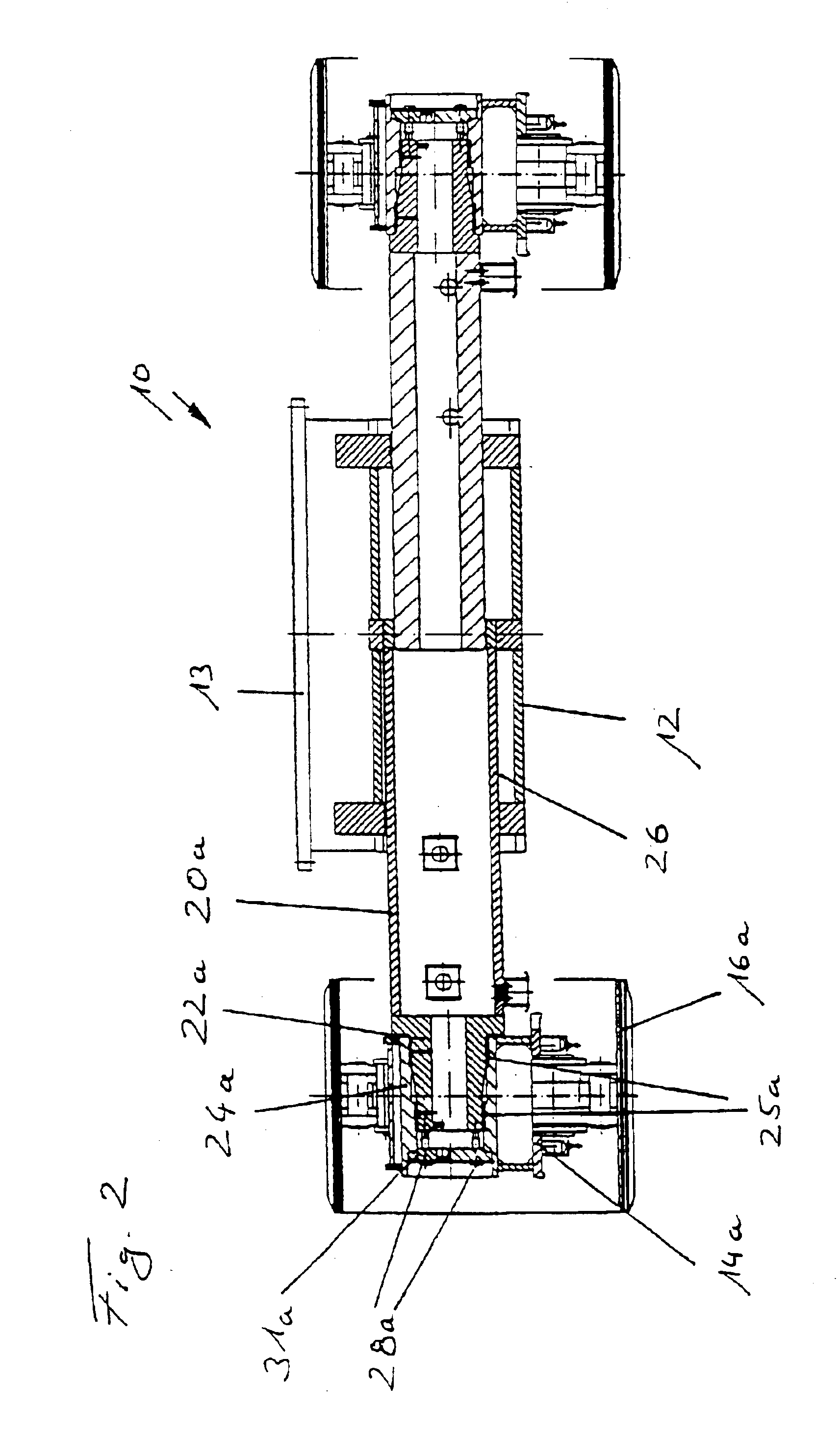
The diameter of the mounting hole of the crawler support increases in the direction of the crossbeam. The entrance diameter of the mounting hole is significantly greater than the external diameter of the mounting journal at the free end of the crossbeam. This conical arrangement of the mounting journal and the mounting hole permits an easy insertion of the mounting journal in the mounting hole during crossbeam displacement. Thus, initially the crawler support does not have to be precisely adjusted with respect to the crossbeams. In fact a precise centering is only obtained during crossbeam displacement and on inserting the mounting journal in the mounting holes. In the extended end position the mounting journals in the correspondingly constructed mounting holes form a positive fit. The fit areas can be formed by cylindrical areas on the mounting journal and mounting hole. This ensures a centering of the crawler supports on the crossbeams. After precisely adjusting the crawler supports to the crossbeams, the crawler supports can be fixed using suitable connecting elements.
According to a preferred embodiment of the invention hydraulic cylinders are provided for crossbeam displacement. The hydraulic cylinders, which can also be used for track width adjustment, on introducing the conical mounting journals into the mounting holes provide the necessary force for crawler support displacement by a few millimeters or even a few centimeters at right angles to the crossbeam movement direction, thereby bringing about centering.
The conically tapering design of the journal is particularly important for bringing about a desired insertion in the correspondingly constructed mounting hole. From the production standpoint, the invention provides for the mounting journal to have a round cross-section. Thus, the mounting journal and the associated mounting hole can be easily manufactured on a lathe or with a milling cutter or drill in the customary way. Round cross-sections also allow particularly high manufacturing tolerances.
For fixing the centered crawler supports to the crossbeams, according to the invention there is a screw connection for a non-positive connection of the crawler supports to the crossbeams. As the tonne-weight crawler support is precisely centered after inserting the mounting journals in the mounting holes, the threaded bolts can be easily used in the aligned through bores and tapped holes. For securing the individual threaded bolts, it is possible to use retaining rings and guards.
It is also advantageous according to the invention that for fixing a track width in each case a connecting pin is provided between the crossbeam and mid-section. Corresponding to the possible and normally standardized track widths, the crossbeams contain through holes, which can be penetrated by connecting pins. This brings about a reliable positioning of the crossbeam on the mid-section.

Problems solved by technology

However, at construction sites, attaching the crawler supports to the crossbeams can be very difficult, since the crawler supports, which are several meters long and weigh several tons, must be precisely adjusted with respect to the crossbeams so that the holes in the perforated plates are aligned with the threaded bolts.
Such a precise setting is time consuming.
It is also difficult to produce a precise bevel.

Method used


Image

  • Crawler running gear
  • Crawler running gear
  • Crawler running gear

Examples


Embodiment Construction

The invention is described in greater detail hereinafter relative to preferred embodiments and the attached drawings, wherein show:

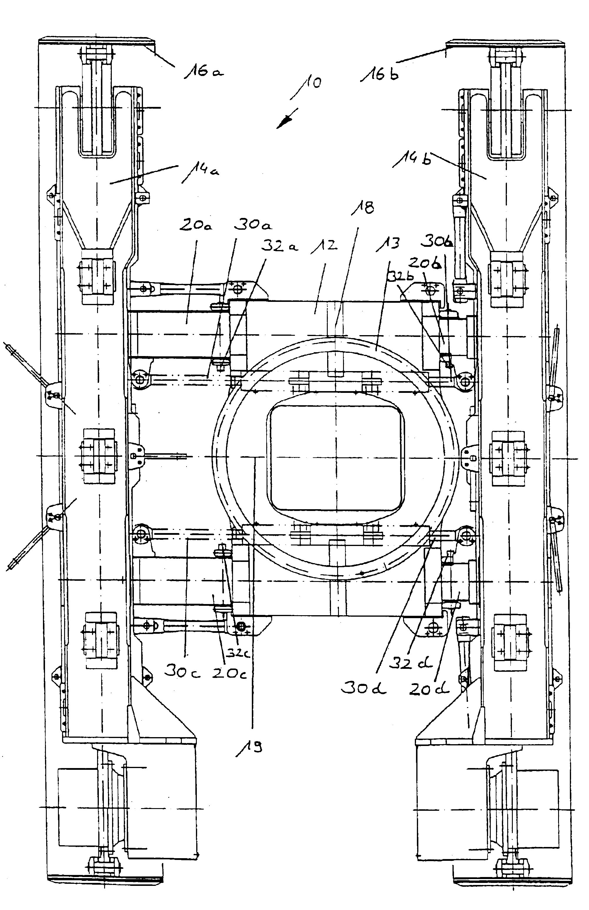
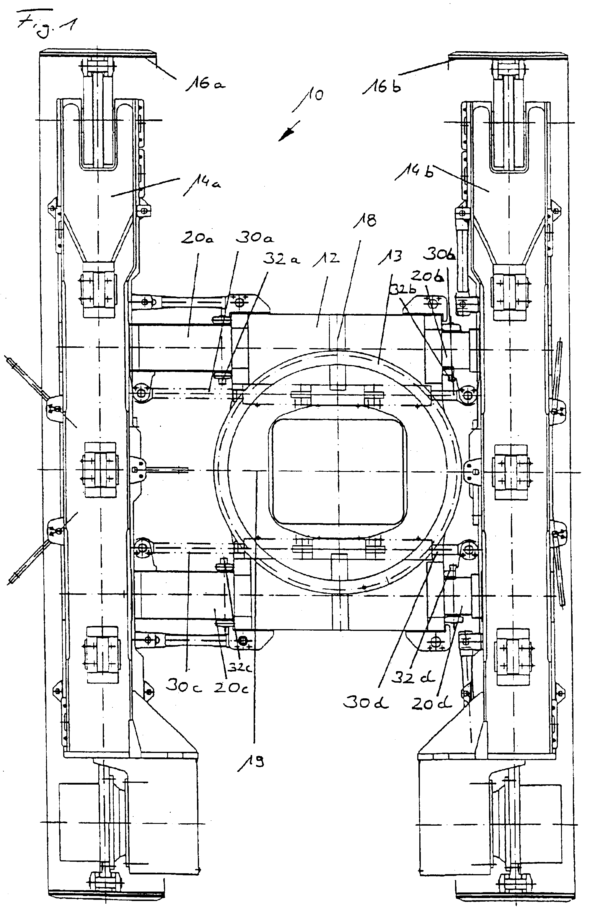
FIG. 1 A diagrammatic plan view of a crawler running gear according to the invention.

FIG. 2 A diagrammatic cross-sectional view through the crawler running gear according to FIG. 1 on crossbeams.

FIG. 3 A modified cross-sectional view through a crawler running gear according to the invention with the crawler supports dismantled.

According to FIG. 1 a crawler running gear 10 according to the invention comprises a box-like mid-section 12, on whose top is located a slewing ring 13 for the rotary reception of an upper chassis. On both longitudinal sides along a longitudinal direction 18 of the crawler running gear 10 are in each case provided one crawler support 14a, 14b each with a respective crawler chain 16a, 16b. The crawler supports 14a, 14b are held by in each case two crossbeams 20a, 20c or 20b, 20d, which are in turn displaceably mounted in the mid-sec...


PUM


Abstract

The invention relates to a crawler running gear, particularly for a construction machine. A mid-section and two crawler supports with in each case a crawler chain are provided. The crawler supports are located along a longitudinal direction on both longitudinal sides of the mid-section and in each case detachably fixed to at least two crossbeams. The crossbeams are displaceably mounted in a transverse direction on the mid-section. For simplifying installation, the crossbeams have on their end directed towards the crawler support an at least zonally conically tapering mounting journal and on the crawler supports are provided mounting holes, which are constructed so as to correspond to the mounting journals of the crossbeams.

Description

BACKGROUND OF THE INVENTIONThe invention relates to a crawler running gear, particularly for a construction machine, with a mid-section and two crawler supports, the crawler supports being located along a longitudinal direction on both longitudinal sides of the mid-section and are detachably fixed to crossbeams, which are displaceably mounted in a transverse direction on the mid-section. Each of the crossbeams has on its end directed towards the crawler support at least one zonally tapering mounting journal for insertion in mounting holes on the crawler supports as well as to a method for the installation thereof.Such crawler running gears are more particularly used in construction machines, e.g. excavators, grabs, cranes, bulldozers, etc. as a result of their good cross-country characteristics. For adjusting the track width it is known to move the two crawler supports along the longitudinal sides of a mid-section. This makes it possible to set a maximum track width in operation, wh...

Claims


Application Information

Patent Timeline
IPC IPC(8): B62D55/08B62D21/14B62D55/084
CPCB62D55/084B62D21/14
Inventor HARTHAUSER, WERNER
Owner BAUER MASCH GMBH
Why Eureka
Eureka Blog
Learn More