System for mounting a machine tool in a holder

a technology for retaining a machine tool and a tool holder, which is applied in the direction of attaching milling devices, manufacturing tools, transportation and packaging, etc., can solve the problems of insufficient centering capability for high-precision machining, insufficient shrink fitting alone, and insufficient degree of rotational restraint, so as to achieve positive restraint of rotation within the tool holder and accurate centered in the tool holder

Inactive Publication Date: 2006-07-18
PARLEC
View PDF17 Cites 20 Cited by
  • Summary
  • Abstract
  • Description
  • Claims
  • Application Information

AI Technical Summary

Benefits of technology

[0010]In a first exemplary embodiment, positive restraint of the tool shank is provided by a first longitudinal flat for engagement with a set screw provided in the tool holder to prevent the tool from being turned in the pocket in use. Preferably, the flat is formed at an angle to the tool axis to assist in retaining the tool axially within the holder. Preferably, a second shank flat opposite the first flat is engaged by a set screw in the holder to assist in orienting the tool correctly during assembly and to permit precise centering of the tool in the aperture. Optionally, the holder may include an axial adjustment means for varying the depth of the aperture as desired, to vary thereby the extension of the tool from the aperture.

Problems solved by technology

Unfortunately, in the prior art either of these criteria may be met, to a high degree of success, but typically not both.
Such mounting means can provide a high level of rotational restraint but inadequate centering capability for high-precision machining.
However, experience in using tools and tool holders in accordance with this invention has shown that shrink fitting alone can be inadequate to restrain the tool from rotation within the tool holder under some high torque loads.

Method used


Image

  • System for mounting a machine tool in a holder
  • System for mounting a machine tool in a holder
  • System for mounting a machine tool in a holder

Examples


Embodiment Construction

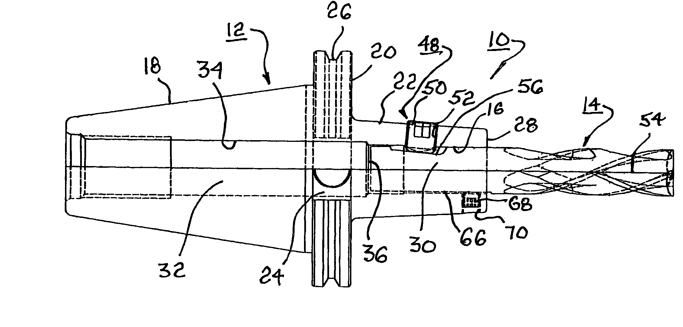
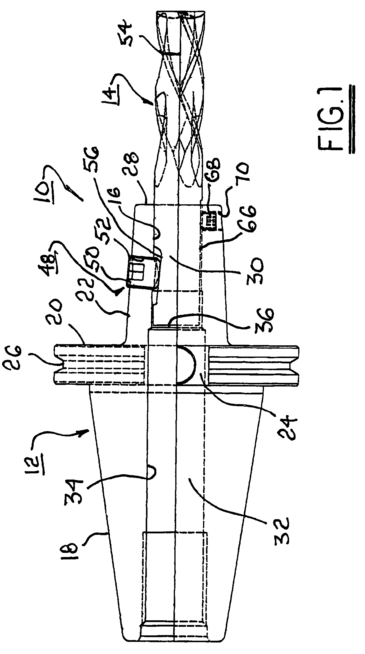
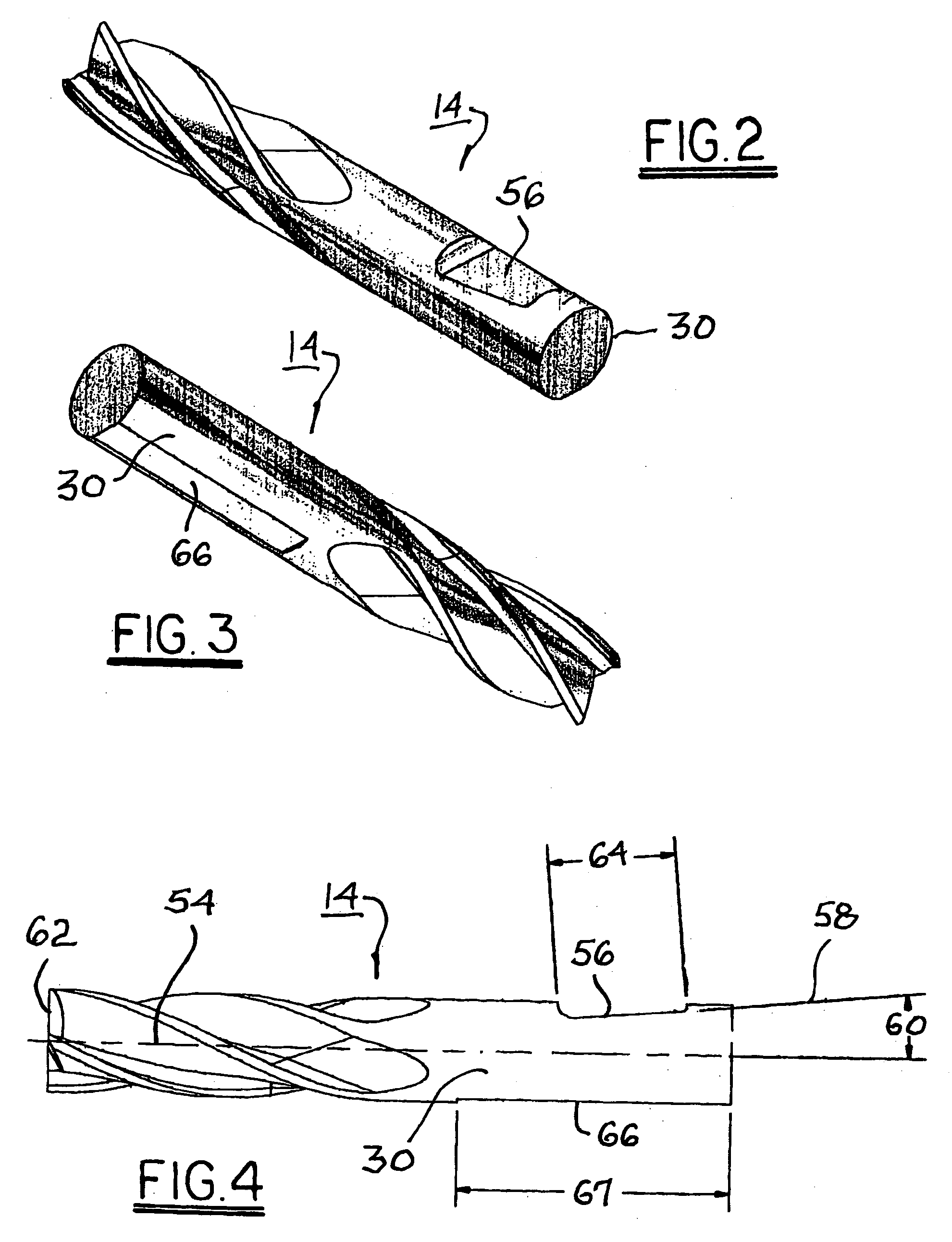
[0022]Referring to FIGS. 1 through 6, a first system 10 for mounting a tool in accordance with the invention includes a tool holder 12 and a tool 14 adapted for holding by holder 12 in a axial aperture 16 in holder 12.

[0023]Holder 12 may be substantially as shown in the '494 patent and is depicted for purposes of explanation herein as comprising a prior art standard Caterpiller V-flange tool holder but additionally may comprise an American standard, European standard DN, or Japanese standard BT type tool holder. As is conventional with all of the standard tool holders, tool holder 12 includes a tapered shank portion 18, a flange portion 20, and cutting tool mounting portion 22. Flange portion 20 includes a pair of mounting recesses 24 as well as a circumferentially-extending V-shaped recess 26. As is well known, recess 26 allows an automated tool holder changer (not shown) to carry and contact tool holder 12 for automatic removal and insertion of holder 12 from the spindle of a mill...


PUM

PropertyMeasurementUnit
angleaaaaaaaaaa
temperatureaaaaaaaaaa
angleaaaaaaaaaa

Abstract

A system for mounting a tool in a tool holder for high-precision centering of the tool and positive restraint of the tool from rotation within the holder. The tool holder includes a cylindrical aperture having a diameter slightly less than the diameter of the shank of a cylindrical tool. The tool is installed into the tool holder by heating the tool holder to a temperature sufficient to increase the aperture diameter sufficiently to accept the tool shank. The tool shank is further provided with an angular flat for engagement with a set screw to prevent the tool from being turned in the holder in use. Preferably, a second tool flat is provided opposite the first flat and extending to the end of the tool shank for orientation of the tool by a second set screw during insertion of the tool into the tool holder.

Description

FIELD OF THE INVENTION[0001]The present invention relates to means for retaining a machine tool in a tool holder for use in a machining apparatus; more particularly, to means for centering and retaining a cylindrical tool in a tool holder; and most particularly, to apparatus for centering and positively restraining a cylindrical tool in a cylindrical opening of a tool holder to a very high degree of centration.BACKGROUND OF THE INVENTION[0002]It is known in the art of tool mounting to dispose a changeable cutting tool in a drivable tool holder provided as part of a cutting machine, for example, a drill press, milling machine, hollow milling machine, lathe, punch press, or the like. In rotating applications, ideally the tool is a) perfectly centered on the axis of rotation of the holder, which is the machine spindle axis, and b) restrained by positive restraint means to prevent the tool from being turned within the holder as a result of torque loads imposed during cutting operations....

Claims


Application Information

Patent Timeline
Patent Type & Authority Patents(United States)
IPC IPC(8): B23C5/22B23P11/02B23B31/00B23B31/02B23B31/107B23C3/00
CPCB23B31/008B23B31/028B23B31/1074B23B31/1075B23B31/1179Y10T279/17957Y10T279/17821Y10T408/95Y10T29/49865Y10T409/30952B23B31/1072
Inventor HARTMAN, DAVID
Owner PARLEC
Why Eureka
Try Eureka