Magnetically driven pump

Inactive Publication Date: 2004-01-06
SIEBEC
View PDF9 Cites 23 Cited by
  • Summary
  • Abstract
  • Description
  • Claims
  • Application Information

AI Technical Summary

Benefits of technology

As regards the evacuation of the calories generated by the rotation, the arrangement described above exhibits an obvious advantage, inasmuch as it produces a thermal bridge with large cross-section and little thickness between the bearing of the driven rotor and the shaft of the motor. Obviously, this advantage is mitigated by the fact that the calories produced by the rotation of the additional connection piece of the shaft of the motor in its own bearing should be evacuated, but this position lies outside the reach of the pumped liquid, which enables to use conventional mechanical c

Problems solved by technology

The first fault that can be ascribed to that type of pump is that the friction pieces forming that joint are exposed to wear and that they must therefore be replaced periodically, which involves downtimes for maintenance purposes.
A second potential fault is the sealing effect properly speaking that cannot be guaranteed perfectly, because of the small surface defects that may be encountered on friction bearing faces, and of the inevitable formation of a liquid film between these surfaces.
These Foucault currents form a heating source that may become prohibitive, notably for large plants.
judicious use of the pumpe

Method used


Image

  • Magnetically driven pump
  • Magnetically driven pump
  • Magnetically driven pump

Examples


Embodiment Construction

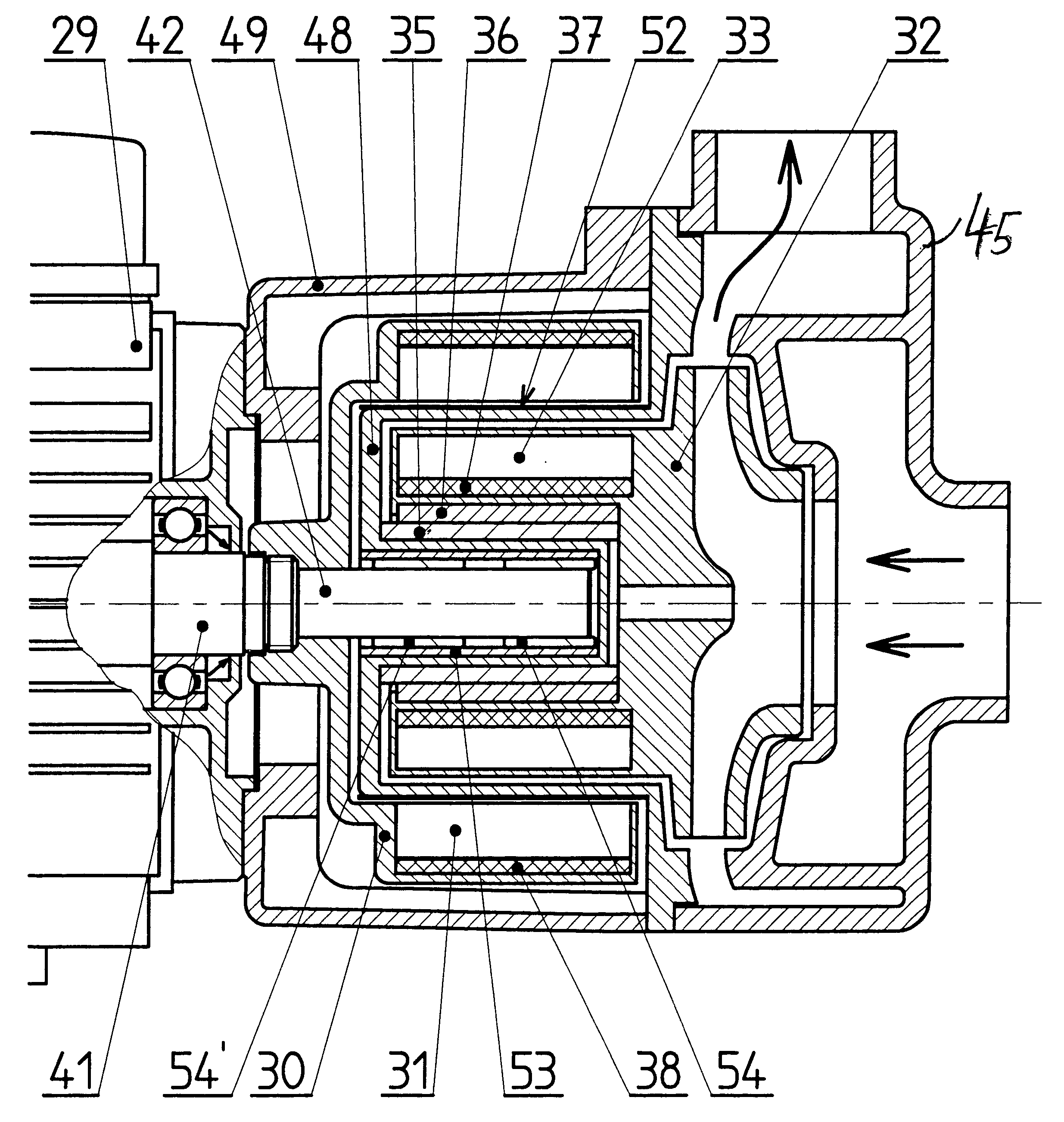
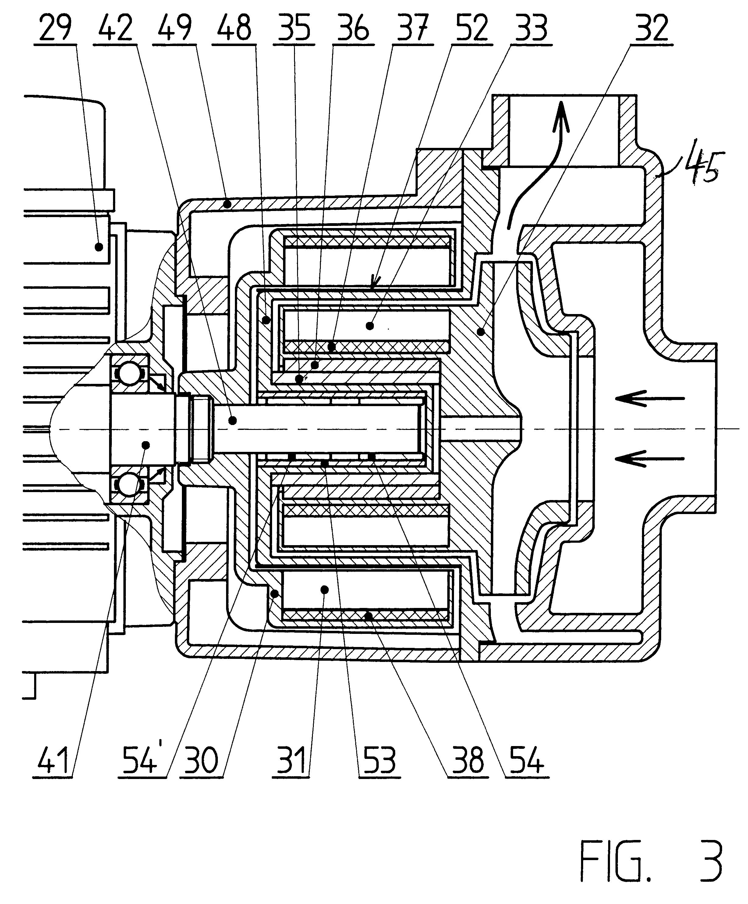
This embodiment is illustrated by FIG. 3 wherein can be seen:

the driving motor 29,

the wheel of the first driven rotor 32, equipped with the first series of magnets 33 and a steel tube 37,

the second driving rotor 30, equipped with the second series of magnets 31 and a steel tube 38, the tubes 37 and 38 being designed for looping the magnetic flux of the permanent magnets 31, 33, the tubes 37, 38 and the magnets 31, 33 are fixed respectively on the second rotor 30 and on the wheel 32 by any appropriate means, notably by duplicate molding,

the fixed ring 35 and the rotating ring 36 forming the rotational bearing of the wheel,

the pump body 45,

and the spacer 49 providing the link between the motor 29 and the pump body 45.

A connection piece 42 lies in the continuation of the motor shaft 41, with which it may be integral, or on which it can be assembled with stiffness and precision. On top of its first function, which is to support and to centre the wheel of the pump, the connection piece 4...


PUM


Abstract

A magnetically driven pump comprises a sealing partition 48 whereof the central portion forms the rotational axis of the rotating portion of the pump, that central portion being itself supported and centered by a rotating connection piece 42 linked to or integral with drive shaft 41 of the motor 29.

Description

The invention concerns a magnetically driven pump comprising:a pump element fitted with a first driven rotor in the form of a wheel mounted to rotate in a body connected to the suction and discharge piping,a first series of magnets integral with the first rotor,a driving motor fitted with a drive shaft on which is mounted a second driving rotor carrying a second series of magnets., both series of magnets being laid out concentrically to provide rotation magnetic coupling,and a sealing device having a fixed partition extending in the gap between both series of magnets while providing tight separation between the pump element and the motor.The sealing partition is particularly important when the pumped liquid exhibits a corrosive nature, which is frequently the case in chemistry or electroplating.For these applications, that do not lend themselves to stoppages readily, it should be noted that maintenance operations must be as short as possible, if not suppressed altogether.PRIOR ARTTh...

Claims


Application Information

Patent Timeline
IPC IPC(8): F04D13/02F04D29/04F04D29/043F04D29/047F16J15/50
CPCF04D29/043F04D29/047F04D13/025
Inventor TERRACOL, CLAUDEVILLETTE, JEAN GUY
Owner SIEBEC
Why Eureka
Try Eureka