
Laryngoscope insertion section

a technology of laryngoscope and insertion section, which is applied in the field of laryngoscope insertion section, can solve the problems of increasing the increasing friction, and difficulty in insertion of a j-shaped insertion section into a patient's oral cavity, so as to facilitate the removal of the endotracheal tube, and reduce the overall bulk of the insertion section

Inactive Publication Date: 2010-10-07
COVIDIEN AG
View PDF23 Cites 39 Cited by
  • Summary
  • Abstract
  • Description
  • Claims
  • Application Information

AI Technical Summary

Benefits of technology

[0020]The first region may extend from the proximal end of the insertion section to the proximal end of the tube guiding surface of the first superior tube contacting member. The first region may extend from the proximal end of the insertion section to the proximal end of the first superior tube contacting member. The first region may include part of the proximal half of the insertion section but not extend to the proximal end of the insertion section. The first region preferably comprises a region of the insertion section which is close to a patient's teeth when the insertion section is fully inserted into a patient, as this can reduce the risk of damage to a patient's teeth.
[0072]As the tube guide is arranged to retain an endotracheal tube such that it is curved at least from where a retained endotracheal tube extends through a patient's teeth when the insertion section is inserted fully into a patient to the first superior tube guiding member, the tube will be easier to insert than would be the case if the endotracheal tube was retained in a generally J-shaped formation and the insertion section will be easier to insert than if the insertion section was arranged in a generally J-shaped formation.

Problems solved by technology

However, a potential disadvantage is that tube guides increase the bulk of the insertion section.
Another problem with known insertion sections with tube guides is that they are typically designed for use with endotracheal tubes of a limited range of sizes.
Firstly, the insertion of a J-shaped insertion section into a patient's oral cavity can be difficult.
Secondly, this arrangement means that, when the endotracheal tube is pushed forward to advance the tube, a resistive force is developed on the superior side of the tube guide where the endotracheal tube bends from being substantially straight to curved, which increases friction.

Method used


Image

  • Laryngoscope insertion section
  • Laryngoscope insertion section
  • Laryngoscope insertion section

Examples


Embodiment Construction

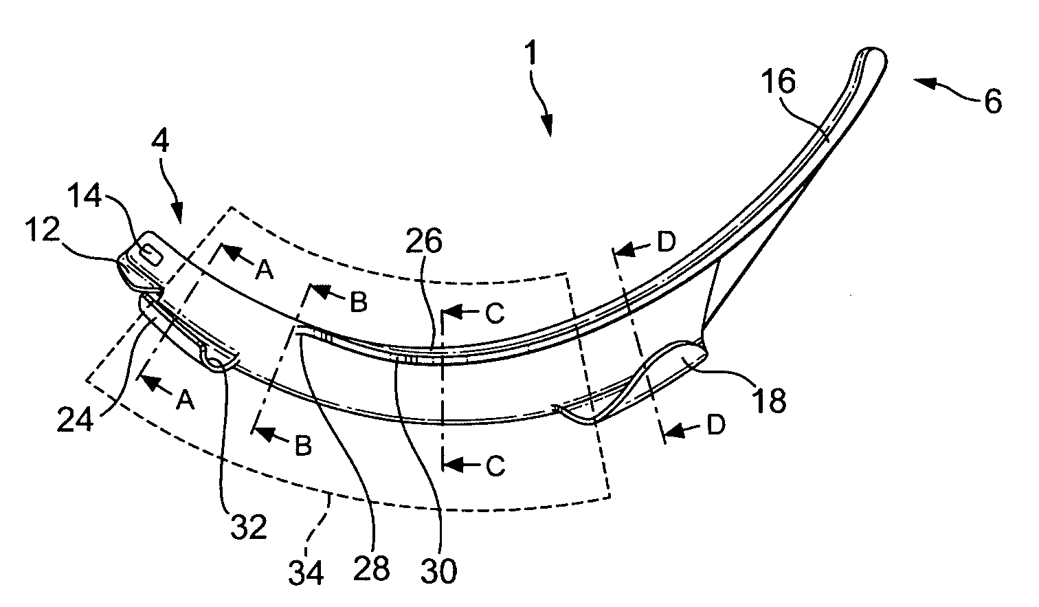
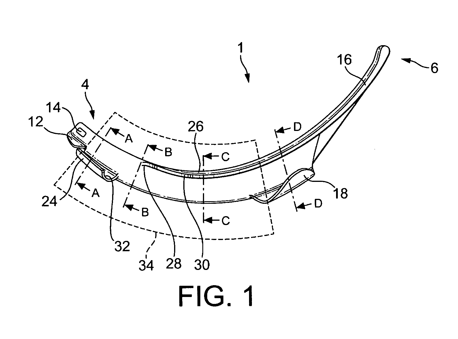
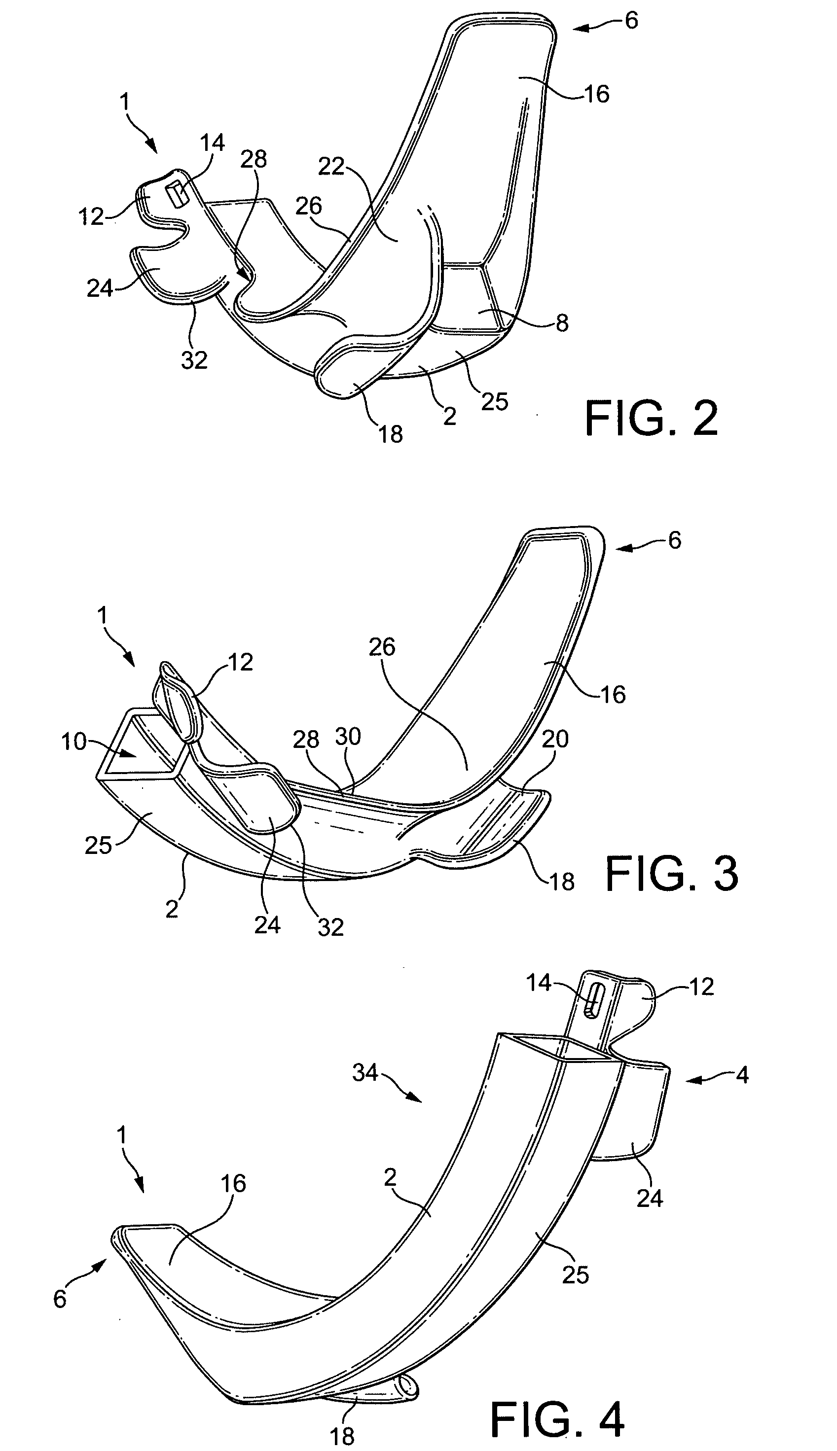
[0101]With reference to FIGS. 1 to 5, a laryngoscope insertion section for use with adult humans, shown generally as 1, comprises an elongate member 2 which extends from the proximal end of the insertion section 4 but does not extend as far as the distal end of the insertion section 6. The elongate member has a light-permeable viewing port 8 at its distal end. An elongate bore 10 extends along the elongate member from the proximal end of the elongate member for receiving and retaining an insertion section retaining protrusion of a laryngoscope and covering the insertion section retaining protrusion to protect it from bodily fluids in use. A retaining portion 12, which includes a fixing aperture 14 for engaging with a corresponding protrusion on an insertion section supporting member of a laryngoscope, facilitates the removable attachment of the insertion section to a laryngoscope. The insertion section may be used with a laryngoscope including a insertion section retaining member wi...


PUM


Abstract

A laryngoscope insertion section comprising a tube guide comprising at least an inferior tube guiding member and a superior tube guiding member, wherein the thickness of the insertion section in a first region is less than the external diameter of the largest diameter endotracheal tube in an operating range of endotracheal tube sizes plus the thickness of the inferior tube guiding member plus the thickness of the superior tube guiding member. Typically, the insertion section comprises an elongate member and the tube guide is lateral of the elongate member. Typically, an endotracheal tube is retained within the tube guide in flexural tension.

Description

FIELD OF THE INVENTION[0001]The invention relates to the field of laryngoscope insertion sections which include a tube guide for detachably retaining an endotracheal tube and guiding a retained endotracheal tube towards a patient's larynx.BACKGROUND TO THE INVENTION[0002]Laryngoscopes comprise insertion sections, which are the elongate part of a laryngoscope which extends towards and into a patient's oral cavity during intubation. Insertion sections may be removably attachable to a laryngoscope body, integral parts of laryngoscopes or themselves function as laryngoscopes. As well as an insertion section, laryngoscopes typically comprises a handle which is usually elongate and which may be arranged at an angle to the proximal end of the insertion section or generally parallel to the proximal end of the insertion section, or at any angle therebetween.[0003]Some known laryngoscope insertion sections, such as Miller or Wisconsin insertion sections, are substantially flat. However, the i...

Claims


Application Information

Patent Timeline
Patent Type & Authority Applications(United States)
IPC IPC(8): A61B1/267
CPCA61M16/0488A61B1/267A61B1/00066
Inventor MCGRATH, MATTHEW JOHN ROSSWALKER, MORGAN JAMES
Owner COVIDIEN AG
Learn More