Resilient positioning assembly for an axle in a power tool

a technology of positioning assembly and power tool, which is applied in the direction of wrenches, screwdrivers, manufacturing tools, etc., can solve the problems of insufficient positioning of hexagonal shaft, damage to users or bystanders, and wear to both tool shafts

Active Publication Date: 2006-04-18
CHENG MING TA
View PDF4 Cites 42 Cited by
  • Summary
  • Abstract
  • Description
  • Claims
  • Application Information

AI Technical Summary

Benefits of technology

[0007]The primary objective of the present invention is to provide a resilient positioning assembly for an axle of a power tool and has a resilient loop received in an annular recess defined in a peripheral edge of the driving end of the power tool and a ball movably received in a hole in communication with the annular recess so that when the driving end is inserted into an auxiliary tool, the resilient loop is able to help secure the auxiliary tool and when the auxiliary tool is inserted into a slot defined in a side face of the driving end, the ball is able to be rested in a corresponding recess in the auxiliary tool.
[0010]A further aspect of the present invention is that the resilient loop has a height in cross section, which is larger than a depth of the annular recess so that when the driving end is inserted into the auxiliary tool, the resilient tool is able to help secure the auxiliary tool.

Problems solved by technology

However, because the positioning force on the hexagonal shaft (61) to maintain the hexagonal shaft (61) inside the hexagonal slot (53) depends solely on the magnetic element (54), it is not sufficient to secure the hexagonal shaft (61), especially when the movement of the hexagonal shaft (61) is violent.
Still, this structure uses friction between two metal surfaces, which causes wear to both the tool shaft (73) and the axle (70).
As a result, engagement between the axle (70) and the tool shaft (73) is loosed and sometimes may even cause damage to users or bystanders.

Method used


Image

  • Resilient positioning assembly for an axle in a power tool
  • Resilient positioning assembly for an axle in a power tool
  • Resilient positioning assembly for an axle in a power tool

Examples


Embodiment Construction

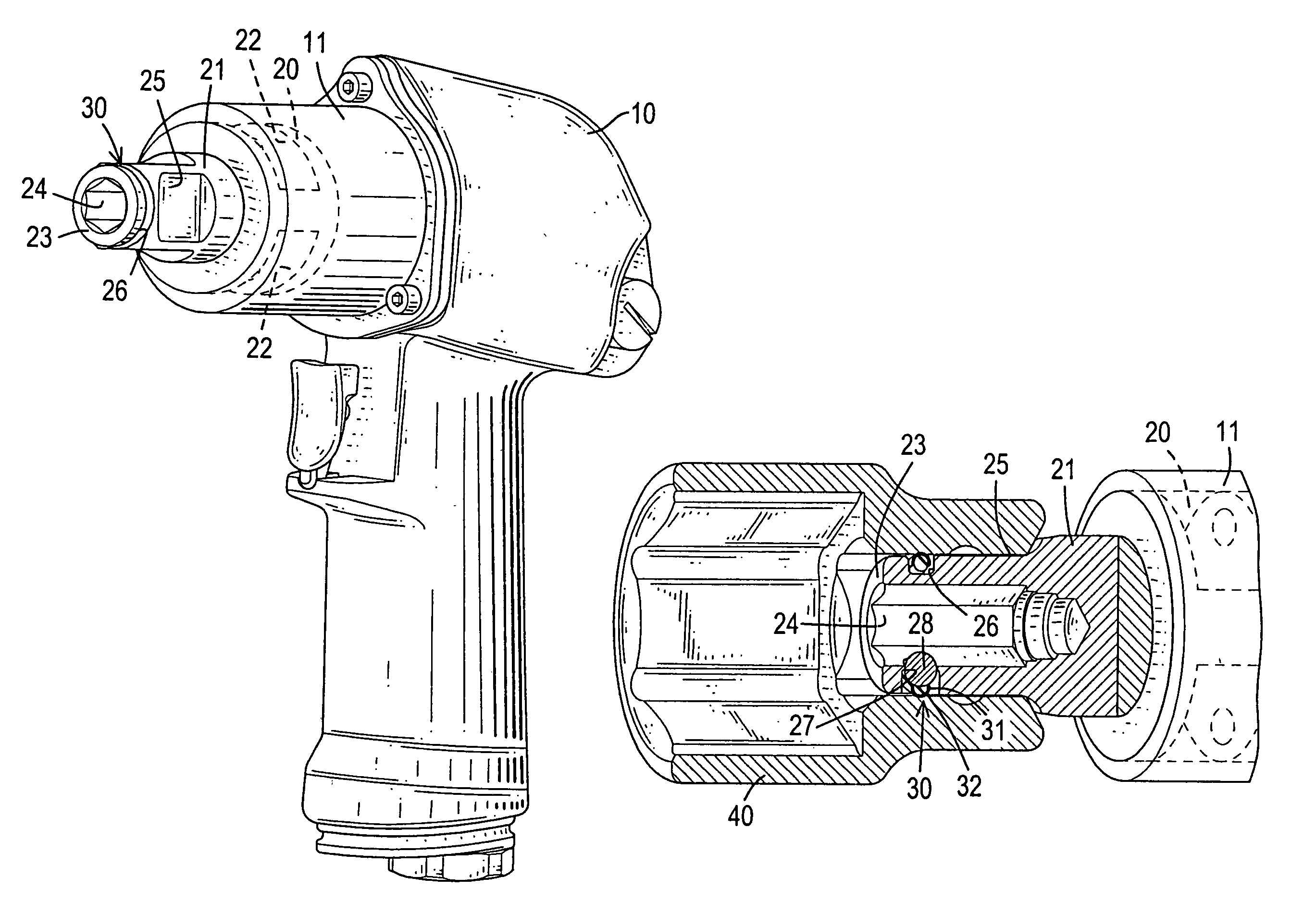
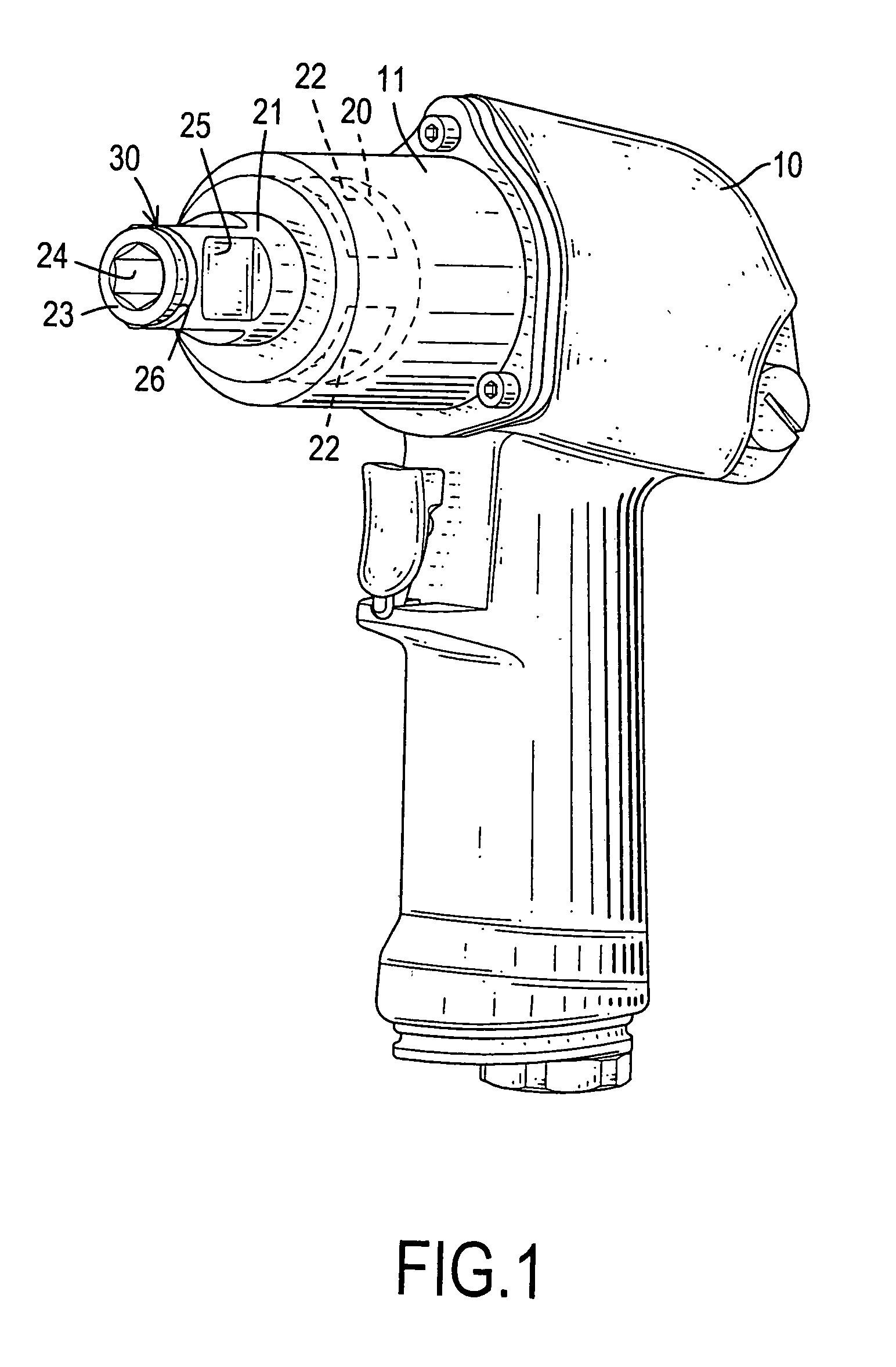
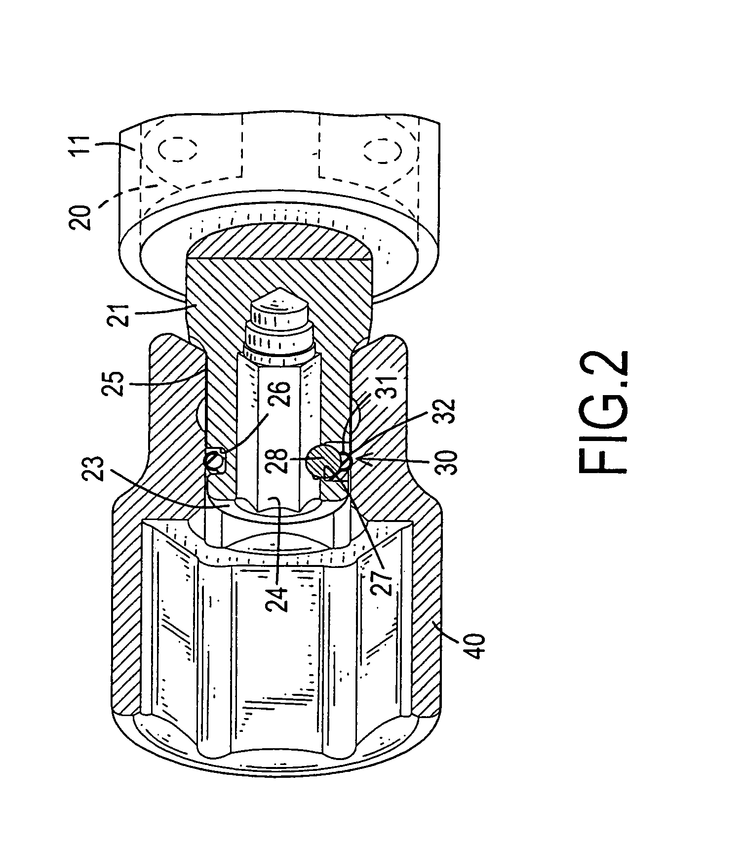
[0017]With reference to FIG. 1, it is noted that a power tool body (10) has an extension (11) extending from a side of the power tool body (10) and an axle extending from a side face of the extension (11). The axle is divided into a fixing portion (20) having a first diameter and multiple mutual corresponding recessed areas (22) defined around an outer surface of the fixing portion and a connection portion (21) having a second diameter smaller than that of the first diameter of the fixing portion (20). Furthermore, the connection portion (21) is divided into a driving end (25) and a peripheral edge (23) formed on a distal edge of the driving end (25) and having a slot (24) defined in the peripheral edge (23). Preferably, the driving end (25) is rectangular and the slot (24) is hexagonal.

[0018]With reference to FIG. 2, it is noted that a positioning hole (27) is defined in a side face defining the slot (24) to communicate with an annular recess (26) defined around the peripheral edge...


PUM


Abstract

A power tool includes an annular recess adapted to be defined in the peripheral edge to receive therein a resilient loop, a slot adapted to be defined in a side face of the peripheral edge and a hole defined in a side face defining the slot to communicate with the annular recess so as to movably receive therein a ball such that engagement between the resilient loop and a first auxiliary tool mounted outside the driving end is secured because of engagement of the resilient loop to an inner face of the auxiliary tool.

Description

BACKGROUND OF THE INVENTION[0001]1. Field of the Invention[0002]The present invention relates to a resilient positioning assembly, and more particularly to a resilient positioning assembly for an axle in a power tool so that the axle is able to adapt to different tools for application.[0003]2. Description of Related Art[0004]A power tool is normally required to be adaptable to for connection with different tools for different purposes. For example, a power tool may be adapted to connect with a socket to tighten or loosen nuts or a power tool may be adapted to connect with a screwdriver to screw or unscrew a screw. With reference to FIG. 4, a conventional positioning assembly (50) in a power tool (60) is shown and has a connection end (51) to connect with an auxiliary tool (not shown), a driving end (52) integrally formed with the connection end (51) to connect to the power tool body, a hexagonal slot (53) defined in a distal end of the connection end (51), a magnetic element (54) re...

Claims


Application Information

Patent Timeline
Patent Type & Authority Patents(United States)
IPC IPC(8): B25B13/04
CPCB25B23/0035
Inventor CHENG, MING-TA
Owner CHENG MING TA
Why Eureka
Try Eureka