
Time-variable magnetic fields generator for a magnetic resonance apparatus

a technology of magnetic resonance apparatus and generator, which is applied in the direction of magnetic variable regulation, process and machine control, instruments, etc., can solve the problems of requiring a significant amount of space and affecting the quality of magnetic resonance images

Inactive Publication Date: 2005-08-16
SIEMENS HEALTHCARE GMBH
View PDF13 Cites 45 Cited by
  • Summary
  • Abstract
  • Description
  • Claims
  • Application Information

AI Technical Summary

Benefits of technology

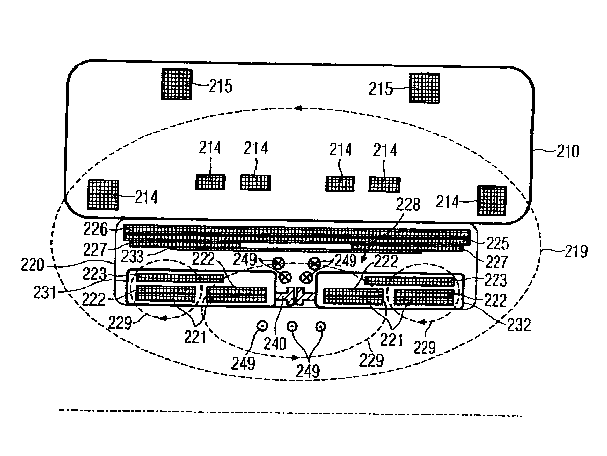
[0013]An object of the present invention is to provide a generator of time-variable magnetic fields of a magnetic resonance device, and a magnetic resonance device with such a generator, in which a device volume that surrounds a predetermined space for exposure of an examination subject can be kept to optimally small dimensions.
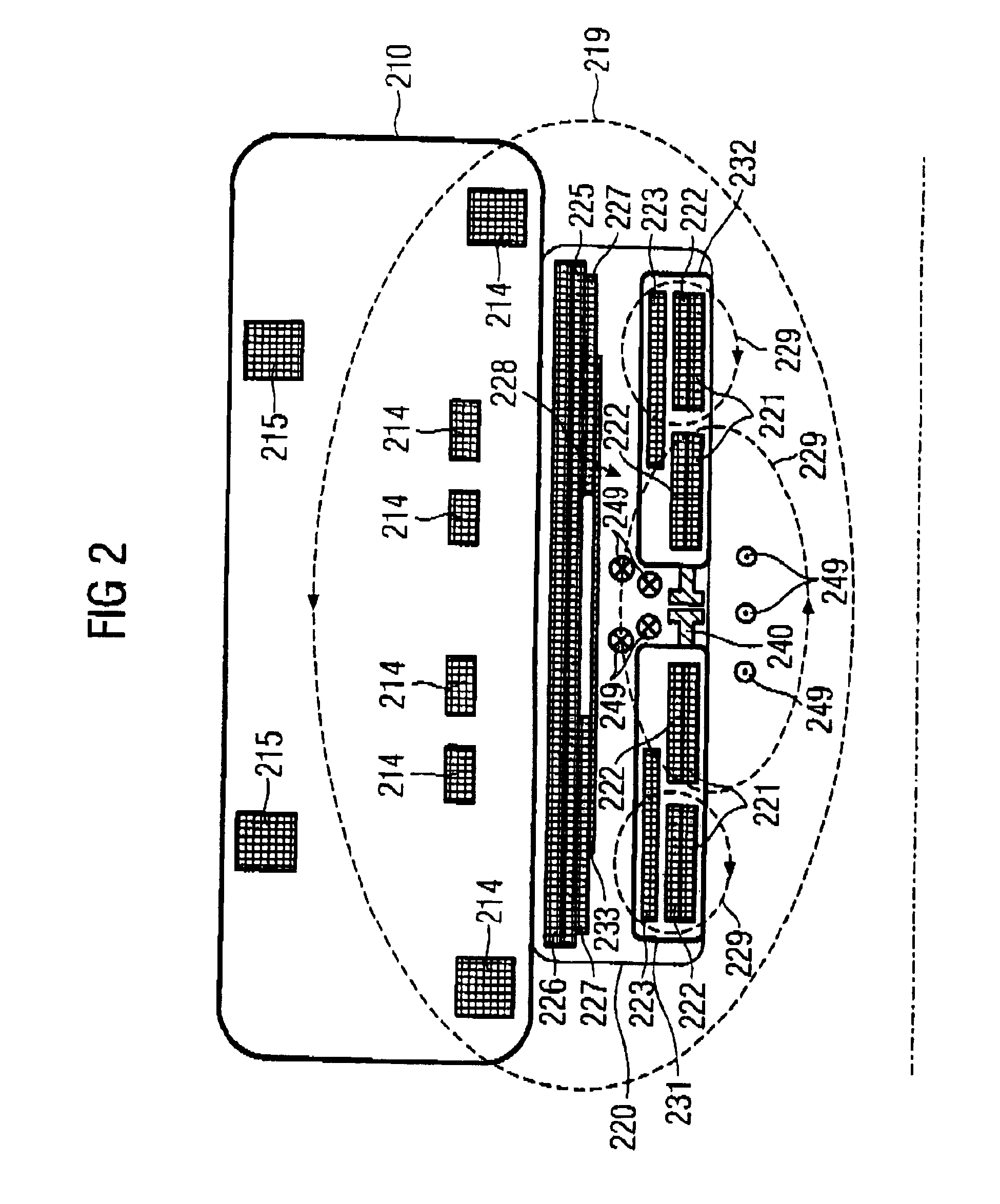
[0015]Due to the inventive design of the generator, a region (not provided in conventional solutions) for return of the radio-frequency field (generated by the radio-frequency antenna element) is provided as a field return space within the gradient coil system having the gradient coil. In contrast to the comparable conventional solutions, the structural combination of the gradient coil system and the radio-frequency antenna can be designed with a smaller external diameter, given a consistent internal diameter, or with a larger internal diameter given a consistent external diameter. In the first case, the basic field magnet of the magnetic resonance device can be dimensioned smaller and thus substantially less costly. In the second case, given an unchanged basic field magnet a larger examination subject acceptance space is achieved that, among other things, increases the patient comfort. These advantages of the invention result, among other things, from the arrangement of the RF antenna element in the middle region, meaning between the first and second RF shields, and thus the space occupied by the gradient coil is optimally (doubly) used.
[0016]A further advantage of the use of a field return space integrated (preferably sealed) in the generator is that the RF field, at least in this region, is uninfluenced by external activities. This allows the RF field to be monitored and, using the monitoring result, more precisely generated. The third RF shield preferably is disposed not only in the region of the antenna element, and thus in the region of the strongest RF field, but also extends on both sides in the axial direction in regions that are radially disposed outside of the gradient coils surrounded by the RF shields.
[0017]In an advantageous embodiment of the generator, the radio-frequency antenna element connects the first and second radio-frequency shields in terms of radio-frequency, such that the first and the second radio-frequency shields, together with the radio-frequency antenna element, form a radio-frequency antenna. This has the advantage that substantial conductor sections of the RF antenna can be formed by conductors (the RF shields) that are anyway present for the gradient coil shielding. This leads to a more compact design of the generator due to the high degree of structural integration of the components used, especially the double use of the RF shields. The connection in terms of radio-frequency can be galvanic or non-galvanic, since in both cases the currents generating the RF field propagate essentially identically in the RF shields. The antenna element typically has a feed-in for an RF signal for RF field generation and / or a read-out for a received MR signal.
[0018]In a further advantageous embodiment, the first and second radio-frequency shields are each connected to the third radio-frequency shield via a connection likewise functioning as a radio-frequency shield, such that the field return space is shielded from radio-frequency up to the middle region. This has the advantage that, in the axial direction, electrical conductors can be displaced lateral to the field return space that also (without further measures vis-à-vis the RF field) do not interact with the RF field. Thus, for example, the gradient coil and a shielding coil associated with it can be connected in series without an inductance in the electrically connected conductors. In special embodiments, the radio-frequency connection of the RF shields can be effected by, for example, the first and / or second RF shield being arranged at least in a region near to the third RF shield, or by the first and / or second RF shield being galvanically connected with the third RF shield via a further RF shield.

Problems solved by technology

The fields arising as a consequence of the eddy currents are undesirable because, without counter measures, they weaken the gradient fields and distort them with regard to their time curve, which leads to impairment of the quality of magnetic resonance images.
Such a design has the disadvantages that it requires a significant amount of space, and that the examination volume of the MR device is determined by the diameter of the RF antenna.

Method used


Image

  • Time-variable magnetic fields generator for a magnetic resonance apparatus
  • Time-variable magnetic fields generator for a magnetic resonance apparatus
  • Time-variable magnetic fields generator for a magnetic resonance apparatus

Examples


Embodiment Construction

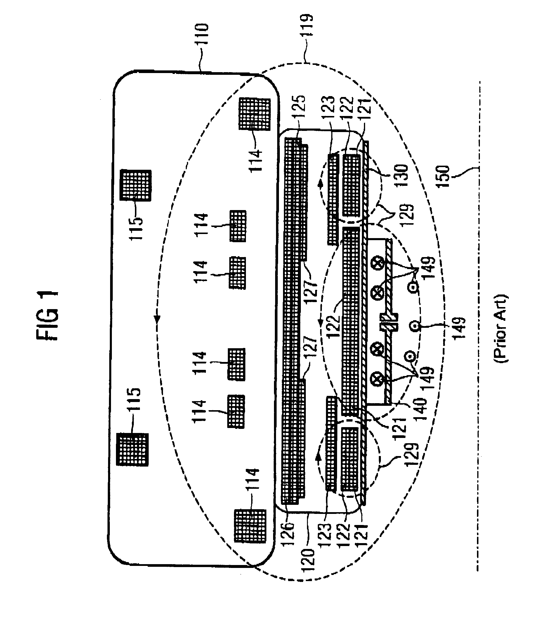
[0026]FIG. 1 shows a longitudinal section through an upper half of a magnetic resonance device with a tunnel-shaped patient acceptance chamber according to the prior art, wherein for clarity only the components in the sectional plane are shown. The magnetic resonance device has an essentially hollow-cylindrical basic field magnet 110 that, to generate an optimally homogenous static basic magnetic field in the patient acceptance chamber, has superconducting primary coils 114 and likewise superconducting shielding coils 115 associated with the primary coils 114.

[0027]A likewise essentially hollow-cylindrical gradient coil system 120 to generate rapidly switchable gradient fields is arranged in the cavity of the basic field magnet 110. The gradient coil system 120 includes, diagnosed from the inside out, the following elements that are concentric to one another in essentially hollow-cylindrical sub-regions of the gradient coil system 120: a first transverse gradient coil 121, formed by...


PUM


Abstract

A time-variable magnetic fields generator for a magnetic resonance apparatus has at least one gradient coil with conductors extending essentially in the region of a subject-receiving hollow opening of the magnetic resonance apparatus, and that is free of conductors in a middle axial region of the hollow opening, a first radio-frequency shield that encloses the conductors disposed on the one side of the middle region, a second radio-frequency shield that encloses the conductors disposed on the other side of the middle region, a radio-frequency antenna element that emits a radio-frequency field, disposed between the first and second radio-frequency shield in the middle region, a third radio-frequency shield proceeding radially, externally around the antenna element, such that the radio-frequency shields delimit a field return space within the generator and that is designed for a return of the radio-frequency field.

Description

BACKGROUND OF THE INVENTION[0001]1. Field of the Invention[0002]The invention concerns a generator of time-variable magnetic fields for a magnetic resonance device with at least one gradient coil, with conductors of the gradient coil extending substantially in the region of a hollow cylinder, and with the gradient coil being free of conductors in a middle region along the axial extent of the hollow cylinder, and a magnetic resonance device with such a generator.[0003]2. Description of the Prior Art[0004]Magnetic resonance technology is a known modality to, among other things, acquire images of the inside of a body of an examination subject. In a magnetic resonance device, rapidly switched gradient fields are generated by a gradient coil system and are superimposed on a static basic magnetic field that is generated by a basic field magnet. Furthermore, the magnetic resonance device has a radio-frequency system that radiates radio-frequency signals into the examination subject to exci...

Claims


Application Information

Patent Timeline
Patent Type & Authority Patents(United States)
IPC IPC(8): G01R33/422G01R33/34G01R33/28
CPCG01R33/34046G01R33/34076G01R33/3415G01R33/422G01R33/385
Inventor HEID, OLIVERVESTER, MARKUS
Owner SIEMENS HEALTHCARE GMBH
Learn More