Tooth brush holder

a technology for teeth and brushes, applied in the field of tooth brush holders, can solve the problems that no prior art discloses the tooth brush holders of the present application, and achieve the effects of minimizing the chance of a malfunction, and minimizing the possibility of water

Inactive Publication Date: 2005-08-02
STRUNK PETER
View PDF16 Cites 41 Cited by
  • Summary
  • Abstract
  • Description
  • Claims
  • Application Information

AI Technical Summary

Benefits of technology

[0017]The preferred shape of the cover of the tooth brush holder is a short cylinder, however, the cover shape may be any shape provided the chosen shape may be rotated to close off the opening of the receptacle. By way of example, but without limitation, the cover may be hemispherical. In addition, various materials may be applied on top of the cover to change the shape, appearance, texture, etc., of the tooth brush holder. Such overlays may be attached to the cover so that the overlay rotates with the cover or such overlays may be independent of the cover such that they do not rotate at all or rotate at a different speed or in the opposite direction from the cover. In addition, the cover material or overlay material may have openings that, when combined with artwork or other features behind such openings, lead to an enhanced visual effect. In addition the tooth brush holder may include one or more light sources that may or may not be synchronized with the audio program or specific points of rotation to achieve desired aesthetic effects. Such light sources may be located at virtually any point on the tooth brush holder such as, without limitation, on the base plate, on the rotating cover, or under the rotating cover. Such light sources may be any known light source. In addition, the cover may be made from transparent or translucent materials to further enhance the visual effect of the tooth brush holder.
[0043]In addition to the above, use of an electric tooth brush may require modification of the receptacle. The overall shape of the receptacle may be modified to accommodate the typically larger cross section of an electric tooth brush. In addition, the bottom portion of the receptacle may be modified so that the base of the electric tooth brush is supported above the base of the receptacle to ensure proper drainage and to minimize the accumulation of tooth paste residue on the bottom of the electric tooth brush. Such modification will also reduce the chance of water and tooth paste residue interfering with the charging mechanism in the case of a rechargeable tooth brush.

Problems solved by technology

None of the prior art discloses the tooth brush holder of the present application.

Method used


Image

  • Tooth brush holder
  • Tooth brush holder
  • Tooth brush holder

Examples


Embodiment Construction

[0049]The following description is made for the purpose of illustrating the general principles of the invention and should not be taken in a limiting sense. The preferred embodiments of the invention are disclosed throughout the present application and its incorporations.

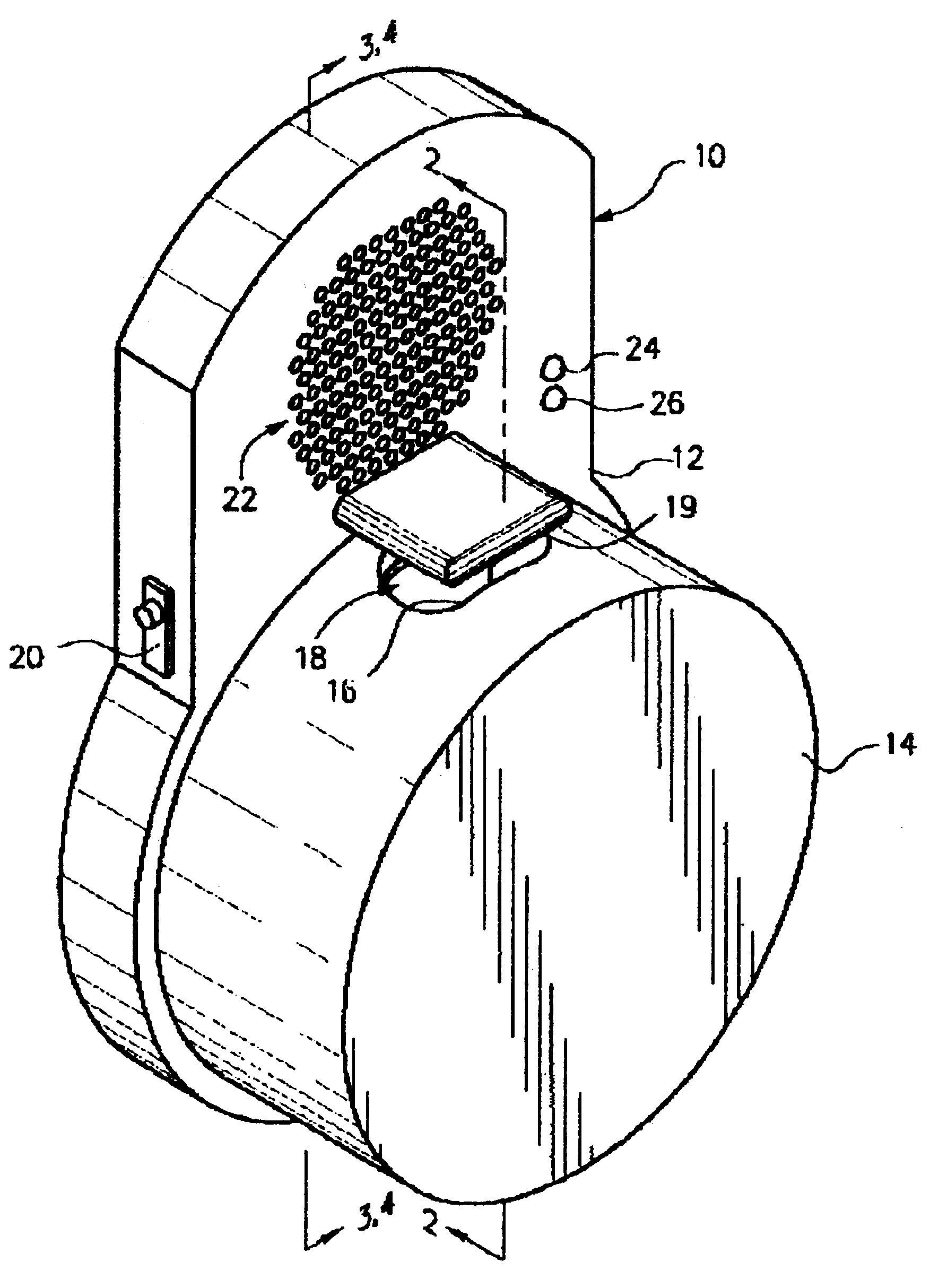
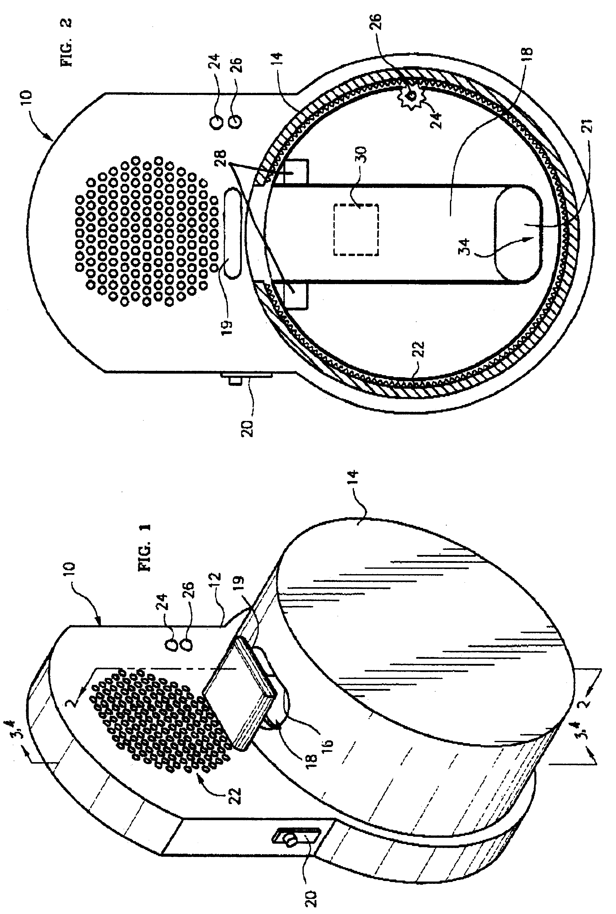
[0050]In accordance with the present invention, FIG. 1 shows an improved tooth brush holder generally designated as 10, having a base plate 12, a rotating cover 14, an opening 16 in the rotating cover, and a receptacle 18 for receiving a tooth brush. FIG. 1 also shows protruding element 19 of a mechanical switch based detecting mechanism. Protruding element 19 blocks opening 16 of cover 14 and receptacle 18 so that a tooth brush (not shown) may not be inserted into the receptacle without moving protruding element 19.

[0051]The dimensions of the receptacle 18 are such that most commonly available tooth brushes will fit whether they are long and slim or shorter and wider. Opening 16 in cover 14 is shown aligned with th...


PUM


Abstract

A tooth brush holder having a base plate, a rotating cover, and a receptacle therein for receiving a tooth brush. The cover has at least one opening in alignment with the receptacle. The base plate includes facilities for closing the receptacle when the tooth brush is removed so that the user cannot replace the tooth brush until a predetermined time has elapsed.

Description

PRIORITY CLAIM[0001]This application is a continuation-in-part application of U.S. application Ser. No. 09 / 494,094, filed Jan. 28, 2000 now U.S. Pat. No. 6,371,420 and is a continuation-in-part of PCT Application No. PCT / US01 / 02592 filed Jan. 26, 2001 and claims priority from both previously filed applications.BACKGROUND OF THE INVENTION[0002]1. Field of the Invention[0003]This invention relates generally to an improved tooth brush holder, and specifically to a tooth brush holder and timer for encouraging the brushing of teeth for a predetermined period of time. The tooth brush holder and timer includes a receptacle for receiving the handle of the tooth brush, means for closing the receptacle when the tooth brush is removed and for keeping the receptacle closed for a predetermined period of time. The subject invention is useful for the improvement of dental health. It is based on three considerations. First, brushing teeth has been proven to be essential to maintain and improve dent...

Claims


Application Information

Patent Timeline
Patent Type & Authority Patents(United States)
IPC IPC(8): A46B15/00G09B19/00A47K1/09
CPCA46B15/0008A47K1/09G09B19/0084A46B15/0002A46B2200/1066A46B17/02A61C17/224G09B23/28G10F1/06
Inventor STRUNK, PETER
Owner STRUNK PETER
Why Eureka
Try Eureka