Motor Vehicle Seat with an Air Supply Device

a technology for motor vehicles and air supply devices, which is applied in the field of motor vehicle seats, can solve the problems of rapid and homogeneous heating or cooling of air flow, unorientated arrangement of spacer threads or spacer webs, etc., and achieves the effect of shallow construction of air supply devices and rapid and homogeneous heating or cooling

Inactive Publication Date: 2009-05-28
DAIMLER AG
View PDF11 Cites 38 Cited by
  • Summary
  • Abstract
  • Description
  • Claims
  • Application Information

AI Technical Summary

Benefits of technology

[0021]In a further preferred embodiment, a centrally arranged air-throughflow layer is surrounded circumferentially by a heating layer. This results in a particularly rapid and homogeneous heating or cooling of the air flow flowing through. In this case, a further air-throughflow layer may be provided on the circumference of the heating layer, in which case, in a preferred embodiment, the air flow flowing through the central layer is heated or cooled to a greater extent than the air flow flowing through the layer arranged circumferentially. This design permits an air flow which can be heated or cooled very quickly and sharply in the central air-throughflow layer, whereas the air flow passing through the outer air-throughflow layer arranged circumferentially has a lower or higher temperature, and, accordingly, adjacent components, such as, for example, a housing wall, cannot be overheated or cooled too severely. It is clear that such a centrically constructed arrangement of air-throughflow layers, with, if appropriate, heating or cooling layers arranged in between, can be expanded as desired. Furthermore, circular, oval, or similar arrangements of the heating or cooling layers are also conceivable.
[0022]The air supply device preferably comprises a blower which is arranged—as seen in the width d...

Problems solved by technology

In the case of open travel, the air flowing over or around the windshield produces, as is known, an “air roll” in the region behind the vehicle seats, the air roll leading to undesirable drafts in the region of the head, neck and shoulder region of th...

Method used


Image

  • Motor Vehicle Seat with an Air Supply Device
  • Motor Vehicle Seat with an Air Supply Device
  • Motor Vehicle Seat with an Air Supply Device

Examples


second embodiment

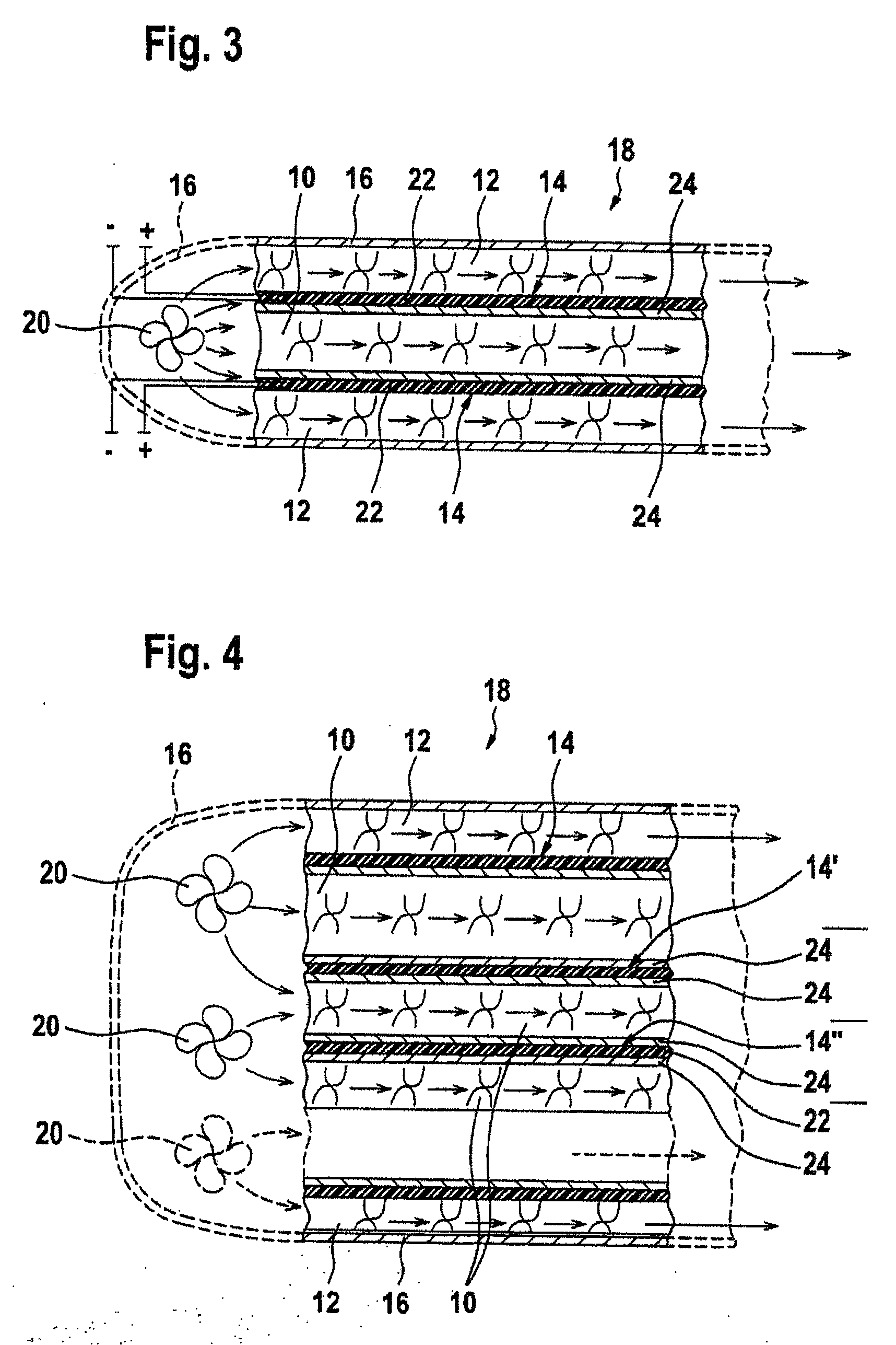
[0048]FIG. 4 shows, in a schematic sectional view, the heating device 5 in which the sandwich 18 comprises a plurality of air-throughflow layers 10, 12 and heating layers 14. As indicated by dashed lines, the sandwich 18 in this case can be supplemented by one or more middle air-throughflow layers 10 and can therefore have a variable thickness. Three middle air-routing layers 10 and, on the outside, in each case an outer air-throughflow layer 12 are arranged in the embodiment shown here, with at least one heating and / or cooling layer 14 being provided in each case between the individual air-throughflow layers 10, 12. The sandwich 24 in this case is once again arranged within a housing 16 and, in the present exemplary embodiment, connected downstream of a plurality of blowers 20. Whereas, in FIG. 4, the uppermost heating layer 14 is identical to the uppermost heating layers 14 according to FIG. 3, the heating layers 14′, 14″ which are second from the top and third from the top, as s...

third embodiment

[0049]FIG. 5 shows, in a schematic perspective illustration, the heating device 5 which is arranged within a housing 16 designed as a tubular air duct. Within said housing 16, a blower (not illustrated), by means of which an air flow illustrated by arrows 26 is generated, is provided upstream of the sandwich 18, explained in more detail further on. The sandwich 18 essentially comprises a heating layer 28 and an air-throughflow layer 30 and is coiled up to form a worm of approximately circular cross section. The air-throughflow layer 30 in this case is designed in such a manner that it completely surrounds the heating layer 28 circumferentially. The heating layer 28 comprises, in turn, a resistance heating ply 22 which is covered on each of its two wide sides by a covering layer 24 preferably composed of a metal foil or a metal sheet. It is clear that, here too, central portions of the air-throughflow layer 30 are flanked on their two wide sides by the heating layer 28. Accordingly,...

fourth embodiment

[0050]FIG. 6a shows, in a schematic cross-sectional view, the heating device 5 in which the sandwich 18 is arranged within a housing designed as a tubular air duct 16. The sandwich 18 in this case comprises a central air-throughflow layer 32 of approximately circular overall cross section, which is surrounded circumferentially by a heating layer 34. The heating layer 34 comprises a covering layer 24 composed of metal sheet or metal foil, which layer adjoins the outer surface area of the air-throughflow layer 32 and is again surrounded on the outside by a resistance heating ply 22. On the outer circumference of the heating layer 34, an outer air-throughflow layer 38 is provided which runs between the heating layer 34 and the wall of the housing 16. It is also apparent here that the centrally arranged air-throughflow layer 32 can be heated to a greater extent than the outer air-throughflow layer 38. The central air-throughflow layer 32 and the outer air-throughflow layer 38 here too ...


PUM


Abstract

In a motor vehicle seat for a closed motor vehicle, an air supply device is provided for supplying the head, neck and shoulder region of the seat occupant with warm air that can emerge via an air discharge opening on that side of the backrest which faces the seat occupant. In order to surround the head, neck and shoulder region of the seat occupant with a draft-free and inconspicuous air cushion or air space, an air discharge opening that extends at least over approximately one third of the width of the backrest of the vehicle seat is provided.

Description

BACKGROUND AND SUMMARY OF THE INVENTION[0001]This invention relates to a motor vehicle seat for a closed motor vehicle, with an air supply device for supplying the head, neck and shoulder region of a seat occupant with warm air.[0002]An air supply device in a motor vehicle seat is already known from German document DE 100 47 754 B4, but this air supply device is particularly suitable for an open motor vehicle. That air supply device has an air discharge opening which is provided on that side of the seat which faces the seat occupant, via which opening a warm air flow for supplying the head, neck and shoulder region of the seat occupant can emerge. In the case of open travel, the air flowing over or around the windshield produces, as is known, an “air roll” in the region behind the vehicle seats, the air roll leading to undesirable drafts in the region of the head, neck and shoulder region of the seat occupant. In order to significantly minimize these drafts, the warm air flow genera...

Claims


Application Information

Patent Timeline
IPC IPC(8): B60N2/56A47C7/74B60N2/90
CPCB60N2/5657B60N2/5635
Inventor MALY, PETERPFAHLER, KARLRENNER, LOTHAR
Owner DAIMLER AG
Why Eureka
Try Eureka