
Automotive seat for mounting child seat thereon

a technology for mounting child seats and seats, which is applied in the field of automotive seats, can solve the problems of no prior technical solution, no small space (l) can be achieved, and the foam padding is easy to deform into an objectionable shap

Active Publication Date: 2007-10-16
HONDA MOTOR CO LTD
View PDF5 Cites 54 Cited by
  • Summary
  • Abstract
  • Description
  • Claims
  • Application Information

AI Technical Summary

Benefits of technology

[0013]In view of the above drawbacks, it is therefore a purpose of the present invention to provide an automotive seat of the type having a center back portion, which allows a child seat to be lockably connected with the center back portion, while providing a shape retaining effect to that center back portion.
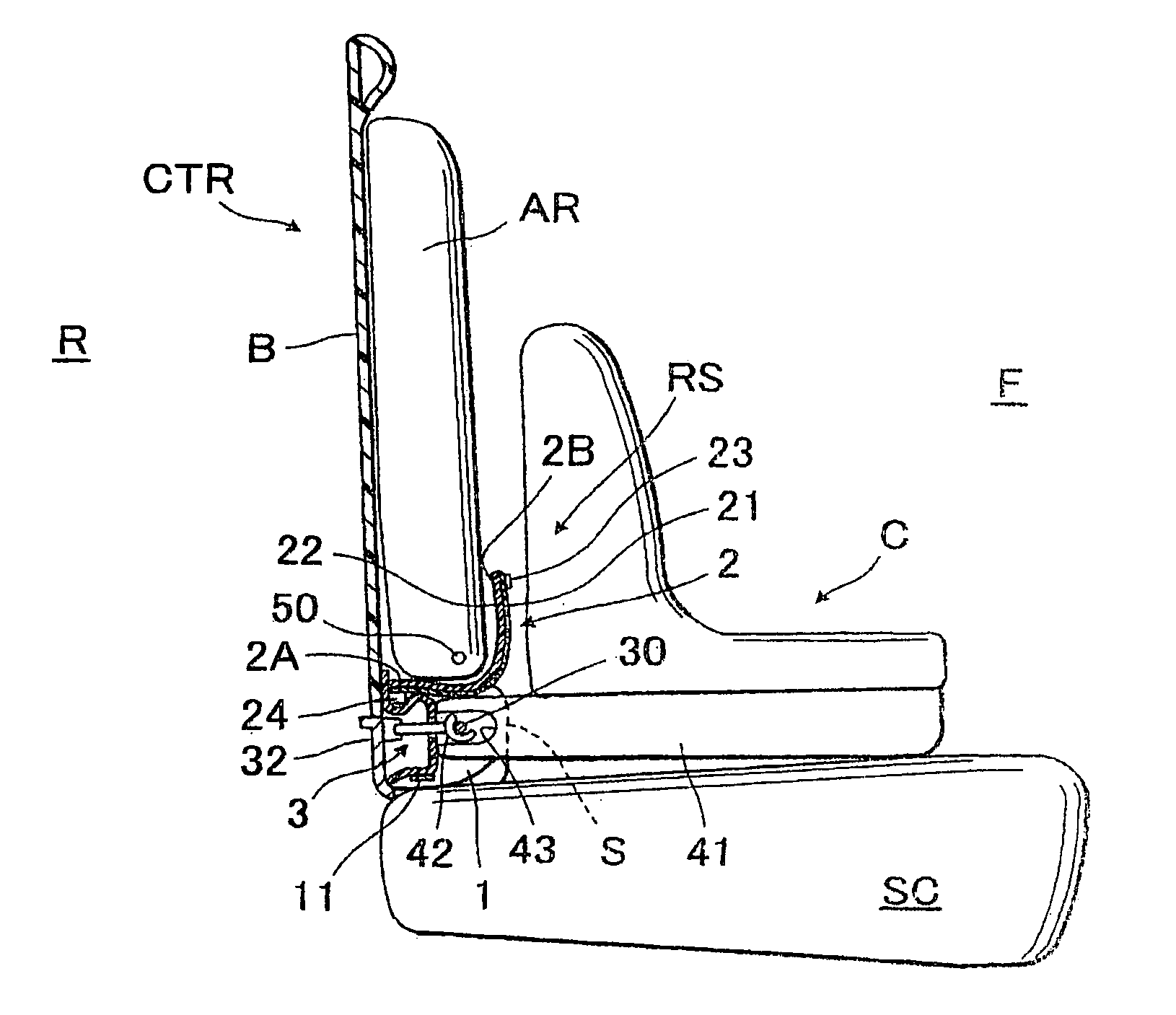
[0022]Accordingly, the forwardly facing surface portion of the hollow support body effectively profides a rigid and undeformable surface sufficient to support a lower body portion of a seat occupant and withstand keen contact of the child seat therewith as well as a load applied from the child seat locked to the shape-retaining / lock element. Further, the cover means, by the reason that it includes the aforesaid one layer of the synthetic resin materil, serves to positively retain a given shape conforming to the shape of the forwardly facing surface portion of the hollow support body and cover the cut-away portion, thus providing an aesthetically improved appearance of the shape-retaining / locking element. Furthermore, the child seat can be easily locked to the center back portion.
[0025]Preferably, the lower wall region may be sloped upwardly away from the seat cushion as it proceeds to the forward curved wall region, thereby allowing easy insertion of user's hands into a space between the hollow support body and seat cushion in order to withdraw and insert the foregoing another end of the cover means from and into a securing point.

Problems solved by technology

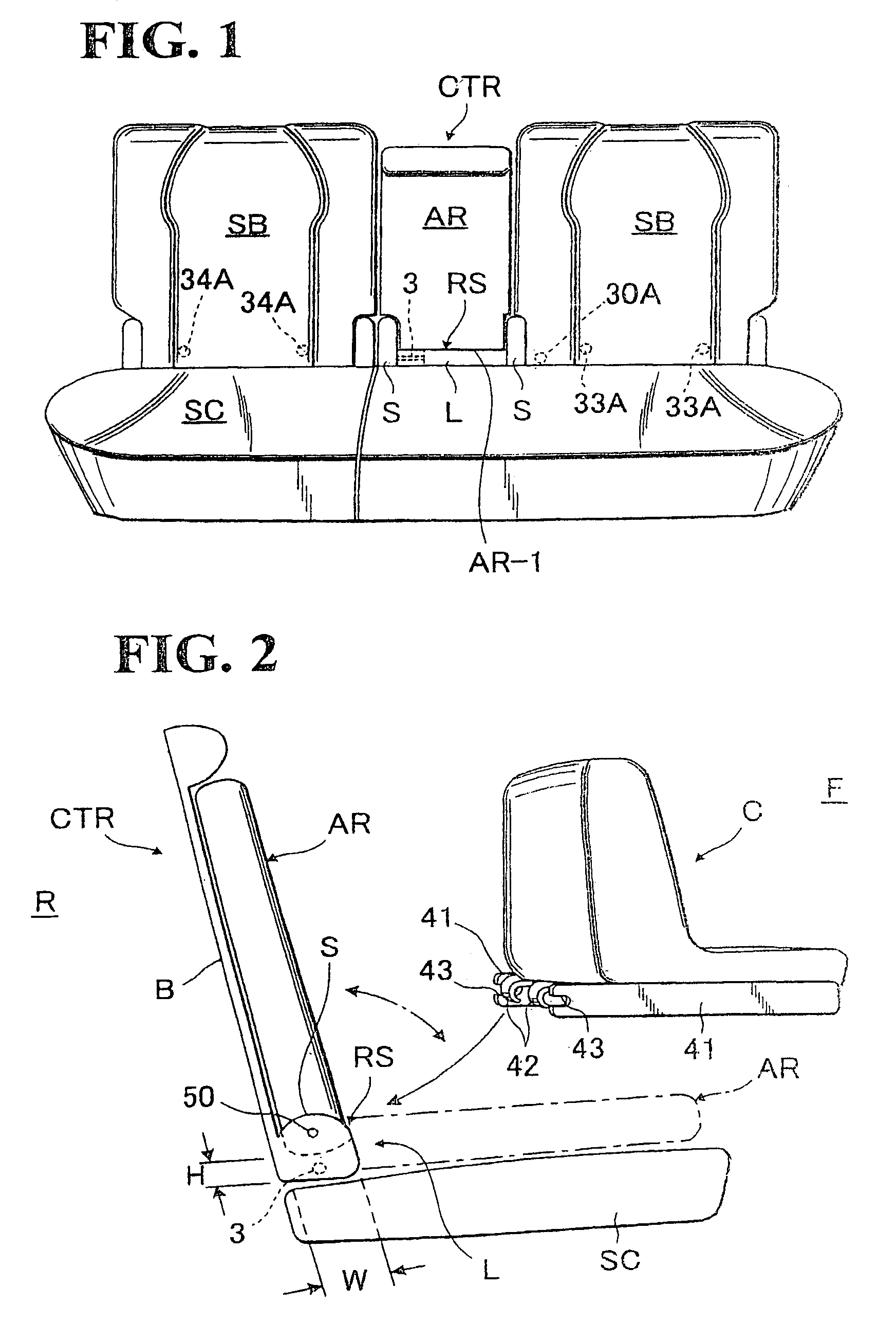
Such small size of space (L) can not be covered decoratively with a foam padding and the like in aesthetic fashion, because the foam padding should inevitably have a small thickness and therefore the foam padding is easy to deform into an objectionable shape.
But, even the Japanese prior art has no disclosure about engagement of the child seat with the center back portion, and there is no prior technical solution thereon.

Method used


Image

  • Automotive seat for mounting child seat thereon
  • Automotive seat for mounting child seat thereon
  • Automotive seat for mounting child seat thereon

Examples


Embodiment Construction

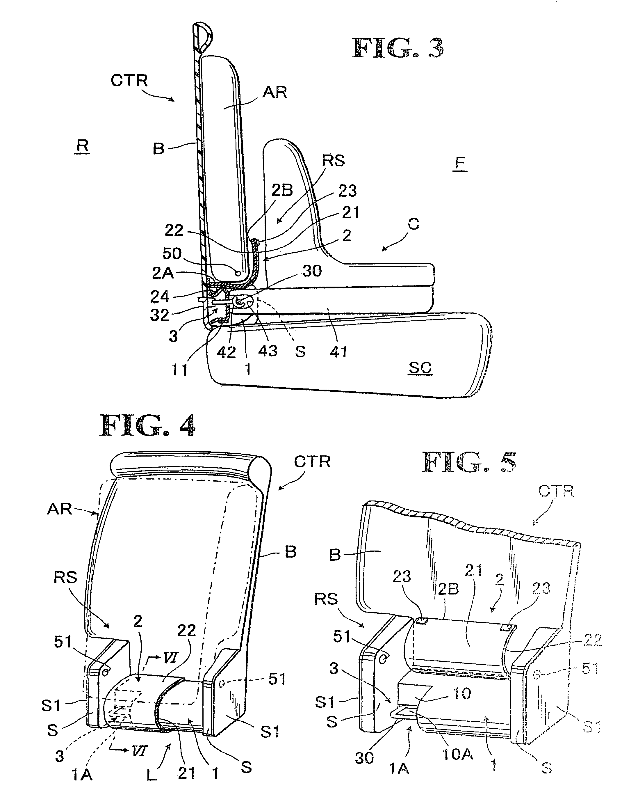
[0035]Referring to FIGS. 1 to 7, there is illustrated a preferred mode of automotive seat of the type allowing a child seat to be mounted thereon in accordance with the present invention.

[0036]FIG. 1 shows a seat for use in an automobile, which is of the type including a pair of seat back portions (SB) (SB) and a center back portion (CTR) defined between the two seat back portions (SB) (SB), wherein an armrest (AR) is rotatably provided to the center back portion (CTR). These seat elements (SB, CTR and AR) are provided on a backward end portion of seat cushion (SC) as shown.

[0037]It is noted that, hereinafter, the wording, “frontal”, “forward” or “forwardly”, refers to a direction toward a forward side (F) of the seat, whereas the wording, “backward” or “backwardly, refers to a direction toward a backward side (R) of the seat.

[0038]The center back portion (CTR) itself is known in the art, and as best seen in FIG. 4, it comprises a back board (B) and a pair of spaced-apart brackets (...


PUM


Abstract

An automotive seat of the type allowing a child seat to be mounted thereon and including a center back portion, wherein a shape-retaining / locking element is provided to a lower region of the center back portion. The shape-retaining / locking element includes a rigid hollow support body; a cut-away portion defined in the support body; a female engagement element to which the child seat is lockably engaged, the female engagement element being exposed outwardly in such cut-away portion; and a cover element for covering the hollow support body and cut-away portion. The cover element includes a layer of hard synthetic resin material with a certain elasticity, such that it normally tends to retain its original shape generally conforming to a forwardly facing surface portion hollow support body. One end of the cover element may be releasably connected to the lower region of the hollow support body.

Description

BACKGROUND OF THE INVENTION[0001]1. Field of the Invention[0002]The present invention relates to an automotive seat which allows a child seat to be securely mounted thereon. More specifically, the invention is directed to an automotive seat of the type having a pair of seat back portions and a center back portion defined therebetween, which provides a shape retaining effect in a lower region of the center back portion and also allows a child seat to be lockably connected with that lower region of center back portion.[0003]2. Description of Prior Art[0004]As shown in FIG. 1, there has been known a rear seat for use in an automobile, which is of the type including a pair of seat back portions (SB) (SB) and a center back portion (CTR) defined between the two seat back portions (SB) (SB), wherein an armrest (AR) is rotatably provided to that center back portion (CTR). Designation (SC) denotes a seat cushion.[0005]As can be seen in FIG. 2, the armrest (AR) is rotatably connected at its l...

Claims


Application Information

Patent Timeline
Patent Type & Authority Patents(United States)
IPC IPC(8): A47D1/10B60N2/90
CPCB60N2/2893B60N2/5816B60N2/4613B60N2/6009B60N2/757
Inventor HAYASHI, SATOSHIPILCHER, KENBLATSEAS, SPYRO G.FUJII, HIROYUKIMITSUMOTO, TOSHINARI
Owner HONDA MOTOR CO LTD
Learn More