Permanent magnet rotor

a permanent magnet and rotating shaft technology, applied in the direction of magnetic circuits, electrical apparatus, dynamo-electric machines, etc., can solve the problems of bursting of the permanent magnet, insufficient circular motion precision, and inability to ensure the reliability of the permanent magnet connection, so as to achieve a simple and cost-effective assembly method

Inactive Publication Date: 2007-12-13
BUHLER MOTOR GMBH
View PDF4 Cites 21 Cited by
  • Summary
  • Abstract
  • Description
  • Claims
  • Application Information

AI Technical Summary

Benefits of technology

[0005] The task of the invention is to ensure that the permanent magnet is mounted securely, that it is not damaged under large temperature fluctuations, and that it is not deflected to an impermissible extent from the rotary axis. A simple and cost-effective assembly method is used in which a secure mechanical connection between the shaft and the permanent magnet is guaranteed over the entire life of the device.
[0006] According to the invention, this problem is solved by arranging the elastic connecting medium on the periphery of the shaft in several first areas in which the distance between the shaft and the permanent magnet is enlarged, and they are separated from the second areas in which the distance between the shaft and the permanent magnet is minimum, but not zero. The areas having larger distance provide secure support to the elastic connecting medium, and the areas with less distance allow only a limited deflection of the permanent magnet with reference to the shaft or a component surrounding the permanent magnet. This increases the precision of the circular motion even under conditions of heavy radial load. The areas with less distance can absorb the volume changes occurring in the elastic connecting medium to a certain extent during assembly or on account of temperature of pressure loads, and thus avoid tensions in the magnet material. Here and in the following pages, shaft also means a rotor body that is integrated with the pump impeller into one single unit, which carries the permanent magnet. The elastic connecting medium is preferably an elastic adhesive. The adhesive creates a compact connection between the shaft and the permanent magnet, which guarantees a stable inner connection between the two components. Silicon was found to be an ideal adhesive with adequate elastic properties. RTV-1 Silicon rubber variants of the ELASTOSIL® series are also suitable, which react to the humidity in the air as an elastic Silicon rubber (RTV-1=Room Temperature Wetting, 1-Component).
[0007] To implement a preferred embodiment of the invention, it is recommended that the elastic connecting medium be arranged in several grooves parallel to the axle. It is also recommended that the number of grooves should not be equal to half the number of poles or the total number of poles of the permanent magnet. Further, the number of grooves should not be equal to the number of wings of the impeller. These measures minimize the noise buildup. To establish a stable connection, the number of grooves should be equal to or more than three, the preferred number being three. The grooves should be distributed at uniform distances on the periphery of the shaft, so that an exact centering of the shaft can be achieved with reference to the permanent magnet. “Wings” have the same meaning as “vanes.”
[0016] Electric motors having a permanent magnet rotor according to the invention are ideal especially for use as pump drives, where the shaft works in tandem with a pump impeller. The shaft and the impeller should preferably be integrated in a single unit. Of course, it is known that the entire pump rotor, i.e., permanent magnet and pump impeller are manufactured from the same material and in one operation, but more permanent material is consumed in this way than is actually necessary. This also has an effect on the weight and the moment of inertia of the pump rotor. Further, it has been established that such one-piece pump rotors can burst under extreme temperature fluctuations, although the permanent material is plastic bound.

Problems solved by technology

However, it is this elastic intermediate layer that prevents a reliable permanent mechanical connection between the shaft and the permanent magnet.
Another disadvantage is that the precision of the circular motion cannot be adequate in case of radial load, because the elastic material is of a yielding variety.
Swelling could lead to the bursting of the permanent magnet.

Method used


Image

  • Permanent magnet rotor
  • Permanent magnet rotor
  • Permanent magnet rotor

Examples


Embodiment Construction

[0024] In describing preferred embodiments of the present invention illustrated in the drawings, specific terminology is employed for the sake of clarity. However, the invention is not intended to be limited to the specific terminology so selected, and it is to be understood that each specific element includes all technical equivalents that operate in a similar manner to accomplish a similar purpose.

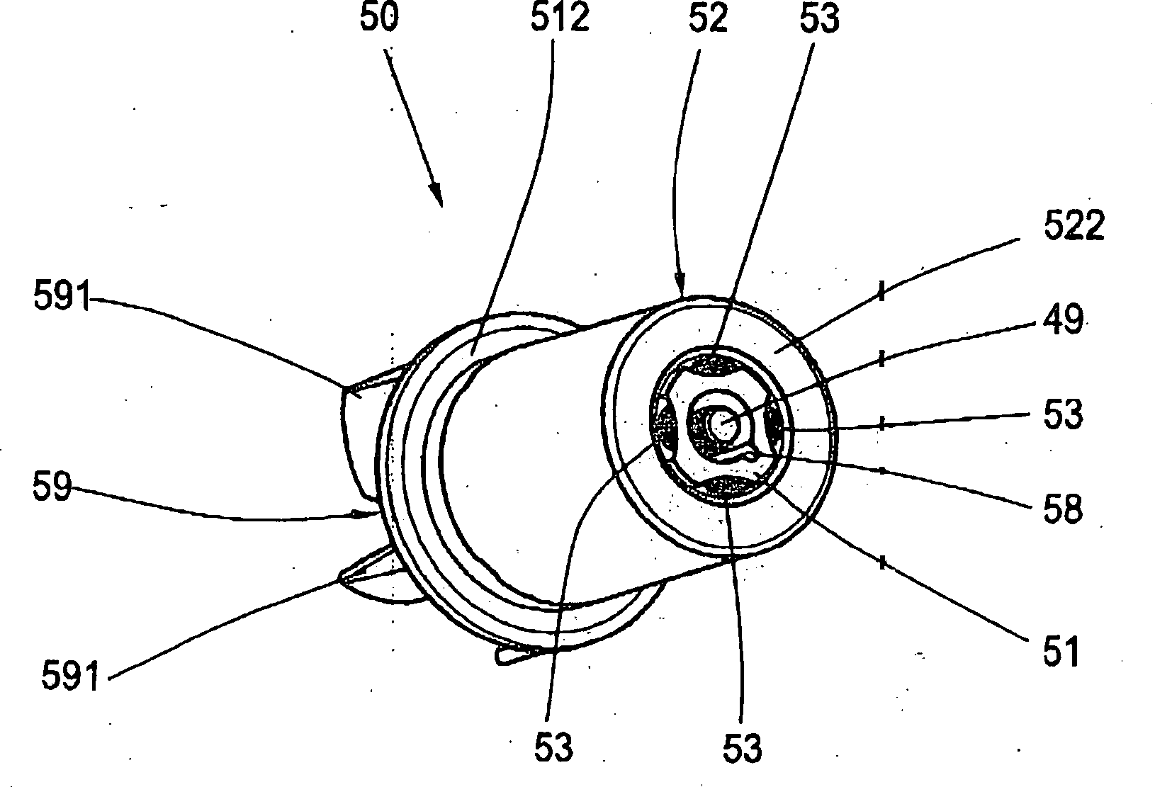
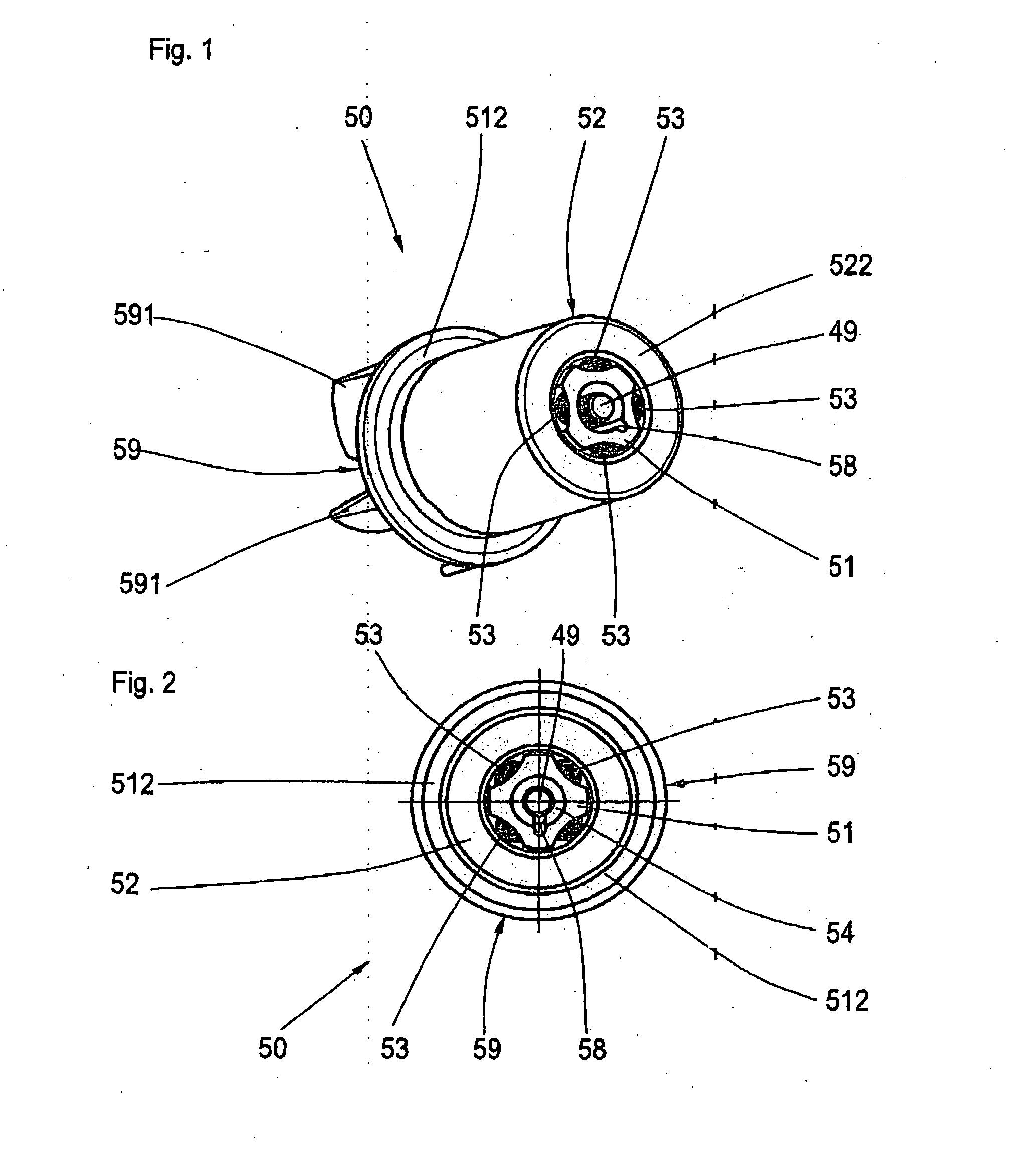
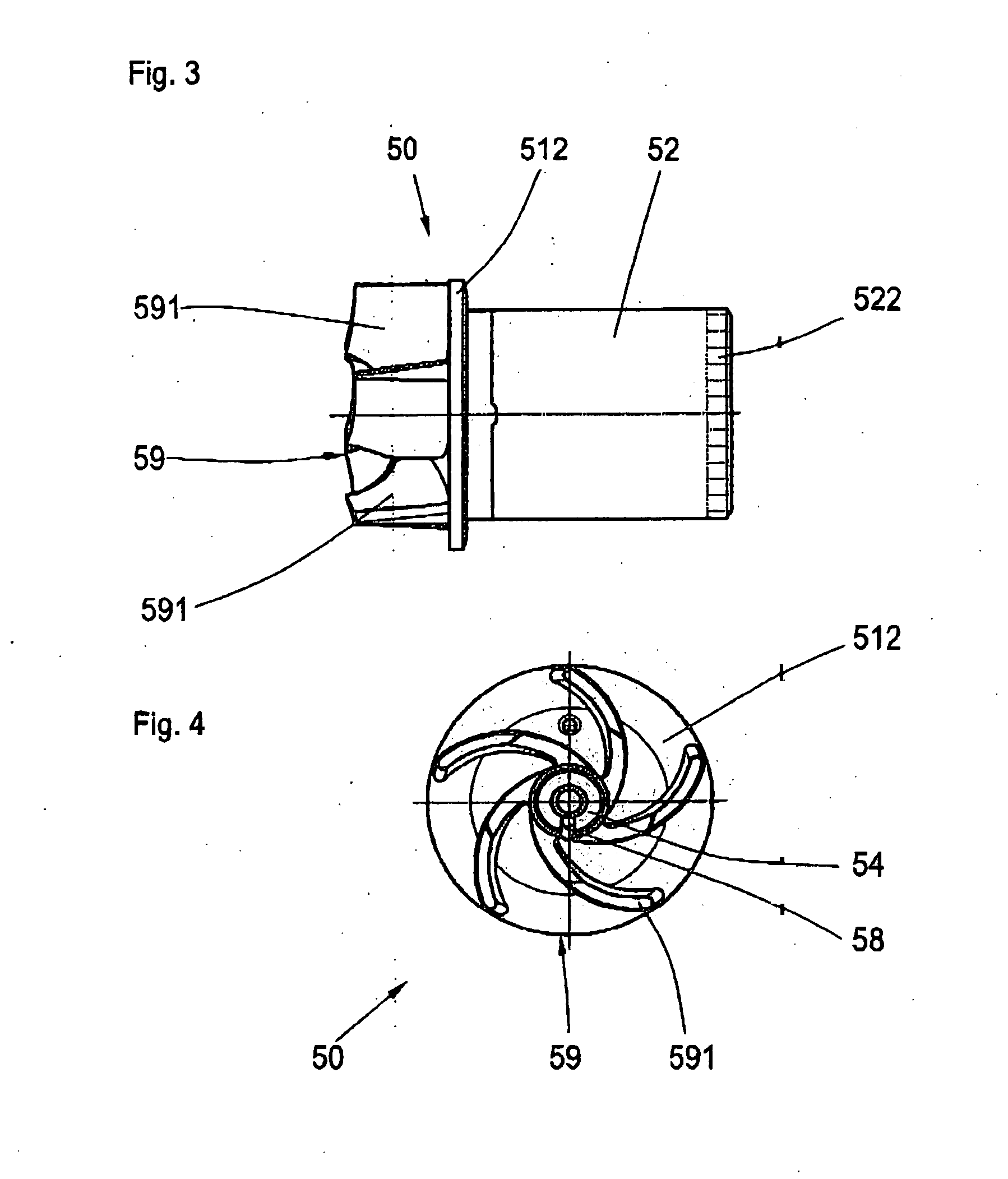
[0025]FIG. 1 illustrates a spatial representation of a rotor 50, which is mounted on an axle 49 through a locating bearing 54. The bearing is connected permanently to a shaft 51 designed as a hollow shaft. The outer periphery of the shaft 51 has four grooves 511 running parallel to the axle. An elastic connecting medium 53 is arranged in the grooves in such a way that it establishes a connection between the shaft 51 and a hollow cylindrical permanent magnet 52. The connecting medium here is an elastic adhesive, e.g., Silicon. The inner diameter of the permanent magnet 52 is slightly mor...


PUM

PropertyMeasurementUnit
distanceaaaaaaaaaa
elasticaaaaaaaaaa
distancesaaaaaaaaaa

Abstract

The invention is related to a permanent magnet rotor having a shaft, a hollow cylindrical permanent magnet and an elastic connecting medium between the shaft and the permanent magnet. The permanent magnet is arranged co-axially around the shaft. The task of the invention is to ensure that the permanent magnet is mounted securely, that it is not damaged during large temperature fluctuations, and that it is not deflected impermissibly from the axis of rotation in case of heavy radial load. A simple and cost-effective installation process is used in which a safe mechanical connection between the shaft and the permanent magnet is guaranteed through the entire life. According to the invention, this task is performed by virtue of the fact that an elastic connecting medium is arranged along the periphery of the shaft at several first areas in which the distance between the shaft and the permanent magnet is enlarged. These first areas are separated from the second areas in which the distance between the shaft and the permanent magnet is minimized but not zero.

Description

BACKGROUND OF THE INVENTION [0001] (1) Field of the Invention [0002] The invention is related to a permanent magnet rotor with a shaft, a hollow cylindrical permanent magnet and an elastic connecting medium between the shaft and the permanent magnet, with the permanent magnet arranged coaxially around the shaft. [0003] (2) Description of Related Art [0004] A generic permanent magnet rotor is known from DE 23 28 886. In this design, a hollow cylindrical permanent magnet is mounted with the help of an elastic intermediate layer. The radial thickness of the elastic intermediate layer is measured in such a way that in case of sudden braking of the motor shaft, the permanent magnet can swing in the direction of the periphery, and thus prevent damage to the gear pinion. Other applications in which there are large temperature fluctuations, elastic intermediate layers help prevent mechanical tensions between materials subject to different degrees of heat expansion. However, it is this elast...

Claims


Application Information

Patent Timeline
Patent Type & Authority Applications(United States)
IPC IPC(8): H02K1/30B29C45/00H02K21/12H02K9/19H02K1/04
CPCH02K1/2733H02K7/14H02K5/128
Inventor IHLE, OLAIPETERREINS, THOMASSCHMIDT, HELMUTSUTTNER-REIHANN, ARMIN
Owner BUHLER MOTOR GMBH
Why Eureka
Try Eureka