Disc brake pad cushions

a disc brake pad and disc brake technology, applied in the field of disc brake pads, can solve the problems of large heat generation between disc brake pads and brake rotors during braking, adversely affecting mechanical and hydraulic systems, and affecting the performance of brake discs, so as to reduce excessive and uneven heat, reduce friction, and simple and cost-effective

Inactive Publication Date: 2007-12-27
ADAMS PHILIP HERBERT
View PDF53 Cites 7 Cited by
  • Summary
  • Abstract
  • Description
  • Claims
  • Application Information

AI Technical Summary

Benefits of technology

[0021] A simple and cost-effective method for reducing the excessive and uneven heat caused by high spot friction is needed.
[0022] A cushion for reducing uneven frictional drag between a disc brake pad and a disc brake rotor caused by irregularities on a friction face of the disc brake rotor is provided. The cushion is comprised of resilient material and is positioned to permit lateral movement of the brake pad as the disc brake pad passes over the irregularities of the friction face. In addition the cushion is further positioned to even the distribution of force exerted by the disc brake pad against the friction face to reduce excessive heating of the brake rotor.
[0023] An apparatus is provided for reducing uneven frictional drag between a disc brake pad and a brake rotor friction face due to irregularities on the brake rotor friction face. The apparatus comprises a brake caliper, a brake rotor having at least one friction face, a brake piston mounted in the caliper, sometimes called a brake caliper piston, for exerting force to press against the brake rotor friction face, a brake pad comprising a backing plate and a friction pad for receiving force from the brake piston to press against the brake rotor friction face, and a cushion disposed adjacent the brake pad backing plate in resilient communication with a force producing element of the brake comprising resilient material for absorbing lateral movement as the brake pad passes over the irregularities on the brake rotor friction face evening the distribution of force exerted by the brake pad against the brake rotor friction face to reduce brake heating.

Problems solved by technology

As designed, the friction between disc brake pads and brake rotors during braking generates large quantities of heat as brake systems convert kinetic energy into heat to slow or stop moving vehicles.
This intense heat can adversely affect mechanical and hydraulic systems.
The problem of heat generation during braking is made much worse than it otherwise would be by irregularities in brake rotors.
As a common problem with disc brakes, irregularities cause generation of excessive heat at brake pad to rotor interfaces.
The problem arises as the rotors are forced between opposing brake pads during braking.
The irregularities cause uneven frictional drag resulting in excessive braking temperatures and in turn resulting in significant adverse effects on braking efficiency and brake system longevity.
The problem is endemic to disc brakes because it is unavoidable that rotors distort during use.
As the high spots on the rotor faces pass between pads applied during braking, severe and excessive frictional drag is produced.
The fact that brake systems are designed to generate tremendous quantities of heat has obscured recognition of the role that rotor high spots play in the generation of excessive friction and heat.
Excessive heat generated by high-spot friction often is the underlying cause of reduced braking efficiency, accelerated brake wear, and other problems.
This lowers friction coefficients, reduces brake system efficiency, and extends normal stopping distances.
.), which results in the dangerous condition known as brake fade or loss of friction.
Accelerated pad wear.
As braking temperatures increase, the rate of wear of brake friction material on brake pads also increases.
Rotors, when used at temperatures above the efficiency threshold, exhibit a greater tendency for scoring, glazing, cracking, and blue-spotting caused by localized hot spots.
The service life of calipers is also shortened by excessive heat.
Excessive heat is the primary cause of caliper boot and seal failure, and is the major factor in caliper seizing caused by heat-compromised lubricants.
Still other problems can be caused by severe frictional drag at high spots, which can be related more directly to frictional drag itself than to the excessive heat it generates.
For example, during even moderate brake applications, because of the severe frictional drag which occurs at rotor high spots, there is an increased danger of one or more wheels locking up.
High-spot friction can become greater than tire-to-road friction, especially when road surfaces are slippery or tires are worn.
This danger becomes acute by the time high spots have grown to such proportions that they are noticeable to the driver as a pulsating pedal.
Another problem is sway.
During any braking cycle, the frictional drag at high spots on rotating rotor faces creates an uneven transfer of braking torque through the tires to the roadway, which reduces vehicle stability and increases the tendency of the vehicle to sway, or exhibit uneven side-to-side stability.
This effect is especially evident on unevenly-loaded or high-bodied vehicles.
The uneven transfer of braking torque through the tires to the roadway also stresses tire assemblies, which causes external tire problems such as cupping and contributes significantly to internal tire problems such as cord separation.
However, this method is usually not used because it would add undesired weight to vehicles and would be prohibitively expensive to implement.
Several devices of this type have been proposed, but these devices are usually designed to absorb hydraulic shock, and do not allow for the role that high spots play in the generation of excessive heat during braking.
However, even if such a device were designed and calibrated specifically to provide optimum high-spot friction compensation, it would likely find reluctant acceptance because of cost and liability issues.

Method used


Image

  • Disc brake pad cushions
  • Disc brake pad cushions
  • Disc brake pad cushions

Examples


Embodiment Construction

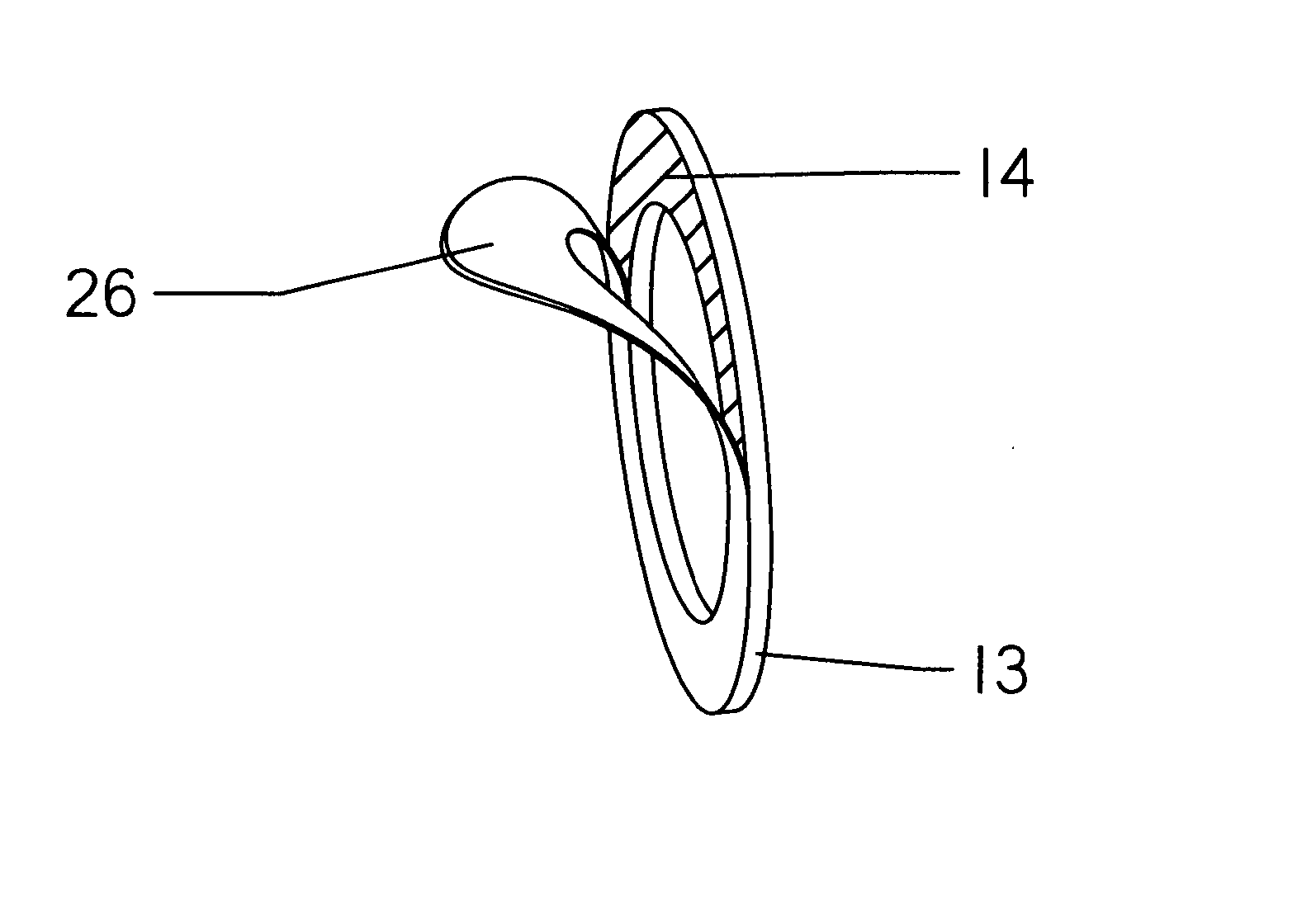
[0038] Severe localized frictional drag can develop in disc brakes as brake rotor irregularities, called high spots, are forced between the brake pads of disc brakes during braking. This can lead to extreme or excessive heating of the rotor, and the excessive heat can be the underlying cause of extended stopping distance, wheel lock-up, accelerated brake wear, tire wear, and other driving safety and consumer issues. Eliminating this source of excessive heating can resolve these problems and other problems associated with the excessive heat caused by high spots on brake rotors.

[0039] Brake systems operate at varying degrees of efficiency until friction interface temperatures reach an efficiency threshold at from about 205 C to about 232 C. Converting to the Fahrenheit scale, these temperatures would be from about 400 F to about 450 F. As interface temperatures continue to climb above this efficiency threshold, brake efficiency drops with the rising temperature.

[0040] The term exces...


PUM


Abstract

Cushions for disc brake pads are disposed between the brake pads and their caliper pistons or caliper fingers. The cushions possess such characteristics of resilience that, during braking action, brake pads follow irregularities and ride over high spots on rotor faces. This action significantly reduces uneven frictional drag, which lowers braking temperature increasing braking efficiency and brake system longevity. Each cushion comprises a resilient body which is further comprised of either a material, such as an elastomeric pad, or a structure such as a compressible spring or other apparatus.

Description

CROSS-REFERENCE TO RELATED APPLICATION [0001] This is a continuation-in-part of co-pending U.S. patent application Ser. No. 11 / 166,569 filed Jun. 25, 2005.BACKGROUND OF THE INVENTION [0002] Disc brake systems are well known, having been used extensively in the automotive industry. These systems are produced in a wide variety of sizes, types, and configurations, but the basic function of disc brakes is to convert kinetic energy, the energy of motion, into thermal energy, or heat. As designed, the friction between disc brake pads and brake rotors during braking generates large quantities of heat as brake systems convert kinetic energy into heat to slow or stop moving vehicles. [0003] Nearly all disc brake systems are comprised of certain basic components. Among them is a caliper that surrounds at least a portion of a brake rotor. Mounted in the caliper are brake pads which are designed to press against the rotor causing the disc brake to slow the vehicle using the brake system. The pr...

Claims


Application Information

Patent Timeline
Patent Type & Authority Applications(United States)
IPC IPC(8): F16D65/78
CPCF16D65/0006F16D2069/007F16D65/0971
Inventor ADAMS, PHILIP HERBERT
Owner ADAMS PHILIP HERBERT
Why Eureka
Try Eureka