Electrode Lead for Medical Use, Insulating Tube and Method for Producing the Same

a technology for electrode leads and insulating tubes, which is applied in the direction of external electrodes, hollow filament manufacturing, insulation conductors/cables, etc., can solve the problems of insufficient electrode lead for many application purposes, and insufficient long-term stability of polyurethane, etc., to achieve excellent bonding strength, high abrasion resistance, and increased abrasion resistance.

Inactive Publication Date: 2012-01-26
BIOTRONIK SE & CO KG
View PDF6 Cites 7 Cited by
  • Summary
  • Abstract
  • Description
  • Claims
  • Application Information

AI Technical Summary

Benefits of technology

[0020]At this point, it should be expressly pointed out that when selecting materials from the stated groups for the base material and the filler material in order to implement the invention, materials having different abrasion resistances should always be selected, with the filler material having a higher abrasion resistance than the base material. This can be done by selecting different material classes, or by selecting different variants of the same, for example, polymer material class. When using different variants of one and the same material class for the base material and filler material, it is possible in some cases to achieve excellent bond strength between the materials of the base material and filler material. The filler material, for example, can be produced from previously cross-linked fibers made of more abrasion-resistant silicone. This filler material can then be admixed to the extrusion compound made primarily of silicone, wherein the filler material does not dissolve because it is already cross-linked.
[0021]The abrasion resistance can, in particular, be increased when the proportion of the filler material in the material of the insulating tube accounts for approximately 0.1% by volume to 30% by volume, and preferably approximately 1% by volume to 15% by volume. Filler material comprising very small particles or fibers (nano-material) is particularly preferably added in lower concentrations in the range of approximately 1% by volume to 5% by volume. As was already explained above, a small proportion of filler material having a higher abrasion resistance is already sufficient in order to significantly improve the properties of the insulating tube with respect to abrasion, without impairing the properties, such as biocompatibility, of the matrix base materials. At these concentrations, the electric insulation of the electrode lead by the insulating tube is also sufficiently ensured when using electrically conductive filler material.
[0022]In a further preferred embodiment, the diameter of the particulate filler material is approximately 1 nm to 100 nm, and preferably approximately 20 nm to 60 nm (nanoparticles). The diameter of the particulate filler material is determined, in particular, by measurement in the SEM (Scanning Electron Microscope). Smaller particles have the advantage that they can be used in smaller quantities for the same effect regarding abrasion resistance. Particularly in the second concentration range that is listed, the particles can still be processed well.

Problems solved by technology

For example, if an electrode lead chafes the collarbone of a person or a second electrode lead (for example, when a plurality of electrode leads are implanted), it is possible that the insulating tube is abraded so far that the functionality of the electrode lead is impaired.
The long-term stability of polyurethane, however, is not sufficient for many application purposes because the material degrades over time.
In addition, such an electrode lead is considerably harder than a single-layer electrode lead having silicone insulation because of the arrangement of two layers on top of each other.
Furthermore, the concept of using an insulation tube made of two coaxially disposed layers is quite complex from a manufacturing engineering point of view.
These materials are so new that no long-term experience data is available yet.
The use of these materials for medical applications is therefore also accordingly complex because of the extensive tests that are required.

Method used


Image

  • Electrode Lead for Medical Use, Insulating Tube and Method for Producing the Same
  • Electrode Lead for Medical Use, Insulating Tube and Method for Producing the Same
  • Electrode Lead for Medical Use, Insulating Tube and Method for Producing the Same

Examples


Embodiment Construction

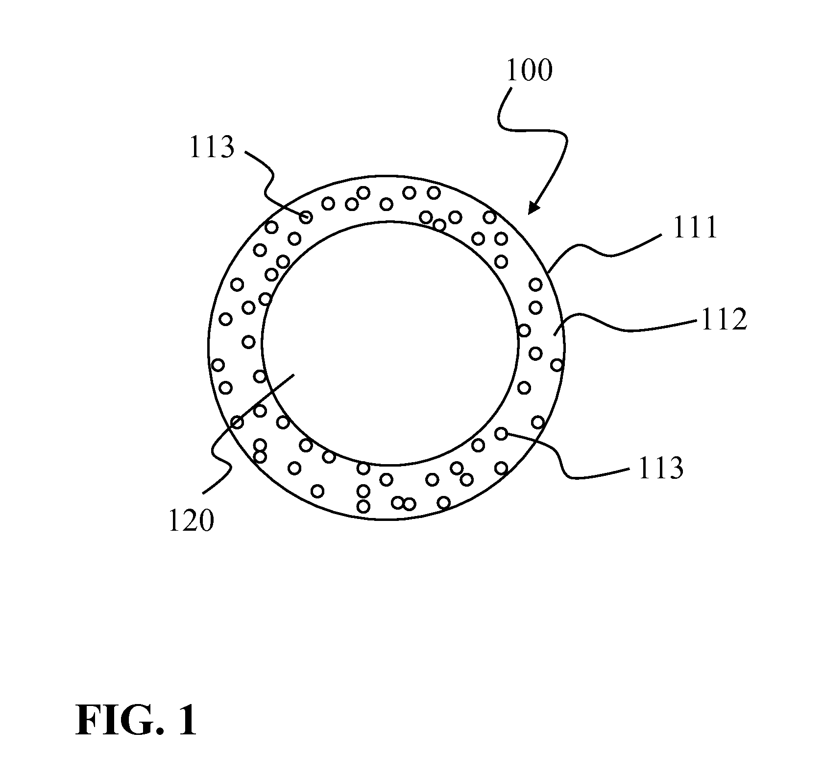
[0066]The insulating tube 100 illustrated in FIG. 1 comprises only a single layer 111, which has a substantially hollow-cylindrical design. The layer 111 is comprised of a base material matrix 112 made of, for example, LSR (liquid silicone rubber), in which the sphere-shaped particles 113, made of, for example, barium titanate, as the filler material are embedded. Such barium titanate particles 113 have an average diameter of approximately 2 μm. As an alternative or in addition, it is also possible to embed tantalum particles as the filler material into the base material matrix. Tantalum particles have an average diameter of approximately 40 μm. The continuous cylindrical opening 120 of the insulating tube 100 is used to accommodate the conductive elements, which at the distal end of the electrode lead form the electrode or electrodes, and at the proximal end form a connecting element for the electrically conductive connection to an electronic system. Both the barium titanate partic...


PUM

PropertyMeasurementUnit
diameteraaaaaaaaaa
diameteraaaaaaaaaa
lengthaaaaaaaaaa

Abstract

An insulating tube for an electrode lead for medical use, particularly a cardiac pacemaker electrode lead, defibrillator electrode lead, electrode lead for nerve stimulation or the like, including a base material made of at least one material of the group consisting of silicones, polyurethanes, polyimide, PTFE, ETFE, and copolymers made of silicones and polyurethanes. In order to improve the functionality of such an insulating tube during friction of the tube with friction partners, at least in one volume region, which preferably forms the lateral surface of the insulating tube, the tube, in addition to the base material, includes a fibrous and/or particulate filler material having a higher abrasion resistance than the respective base material. A corresponding electrode lead is also provided, and a simple and cost-effective method for producing such an insulating tube and such an electrode lead.

Description

CROSS-REFERENCE TO RELATED APPLICATIONS[0001]This patent application claims the benefit of co-pending U.S. Provisional Patent Application No. 61 / 366,529, filed on Jul. 22, 2010, which is hereby incorporated by reference in its entirety.TECHNICAL FIELD[0002]The present invention relates to an insulating tube for an electrode lead for medical use, in particular a cardiac pacemaker electrode lead, defibrillator electrode lead, electrode lead for nerve stimulation or the like, comprising a base material, such as silicone. The present invention further relates to such an electrode lead and to a method for producing an insulating tube for such an electrode lead, and further to a method for producing such an electrode lead.BACKGROUND[0003]Electronic medical systems such as, for example, cardiac pacemakers, defibrillators or neurological devices such as, for example, brain pacemakers for deep brain stimulation, spinal cord stimulation devices, TENS (Transcutaneous Electrical Nerve Stimulato...

Claims


Application Information

Patent Timeline
Patent Type & Authority Applications(United States)
IPC IPC(8): A61N1/05B29C41/24B29C47/00H01B13/06B05D5/12B29C47/02B29C41/30B32B38/08B32B1/08B29C47/06
CPCA61N1/0551Y10T428/1355A61N1/056Y10T428/1372A61L29/126Y10T428/1362
Inventor GUENTHER, THOMASKOLBERG, GERNOT
Owner BIOTRONIK SE & CO KG
Why Eureka
Try Eureka