AI technical title is built by Patsnap AI team. It summarizes the technical point description of the patent document.
a technology for snowboarding boots and bindings, applied in snowboard bindings, transportation and packaging, sport apparatus, etc., can solve the problems of reducing the control of the snowboard during critical maneuvers, insufficient contact between the boot and the binding, and insufficient limited contact, so as to achieve greater security and control, the effect of quick connection and disconn
Inactive Publication Date: 2001-08-21
HOGSTEDT ROY L
View PDF8 Cites 79 Cited by
Summary
Abstract
Description
Claims
Application Information
AI Technical Summary
This helps you quickly interpret patents by identifying the three key elements:
Problems solved by technology
Method used
Benefits of technology
Benefits of technology
It is still an additional object of the invention to provide a snowboard boot and binding which offers greater security and control and quicker connect and disconnect as compared to the prior art.
Problems solved by technology
However, all have deficiencies in regard to the interface between the bindings and the boots.
More specifically, most of the prior art discloses insufficient contact between boot and binding such as only two points or regions of contact on opposing middle positions of the boot.
Such limited contact is inadequate because it permits heel and or toe lift which reduces control of the snowboard during critical maneuvers.
Other prior art provides heel and toe locking, but permits separation between boot and binding along the sides of the boot thereby reducing the security of the interface which detrimentally affects the confidence of the snowboarder.
Moreover, the release mechanism for both types of prior art (i.e., side connections and heel and toe connections), is typically too cumbersome and complex making it either unreliable or too difficult to engage.
Method used
Image
Click on the blue label to locate the original text in one second.
Reading with bidirectional positioning of images and text.
Examples
Embodiment Construction
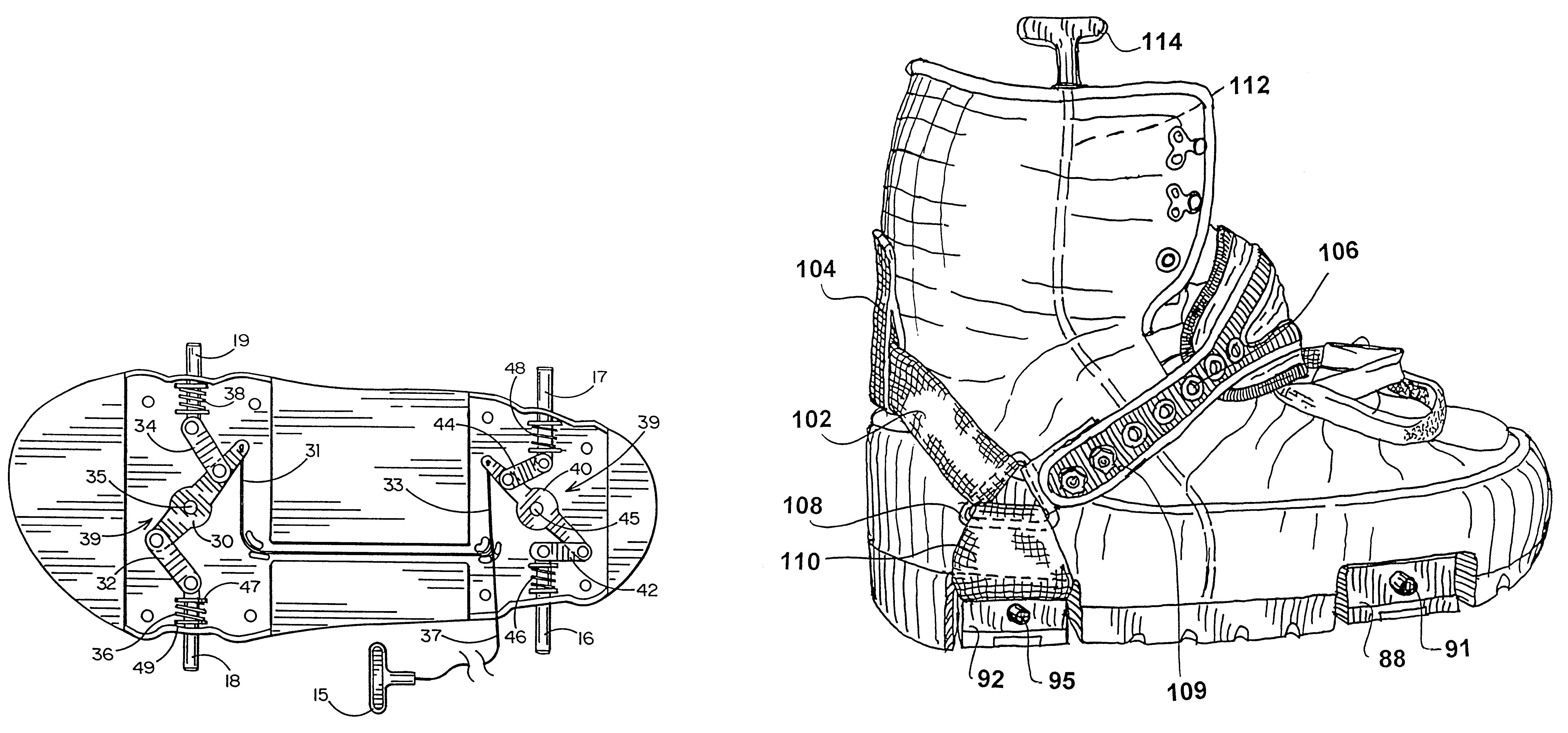
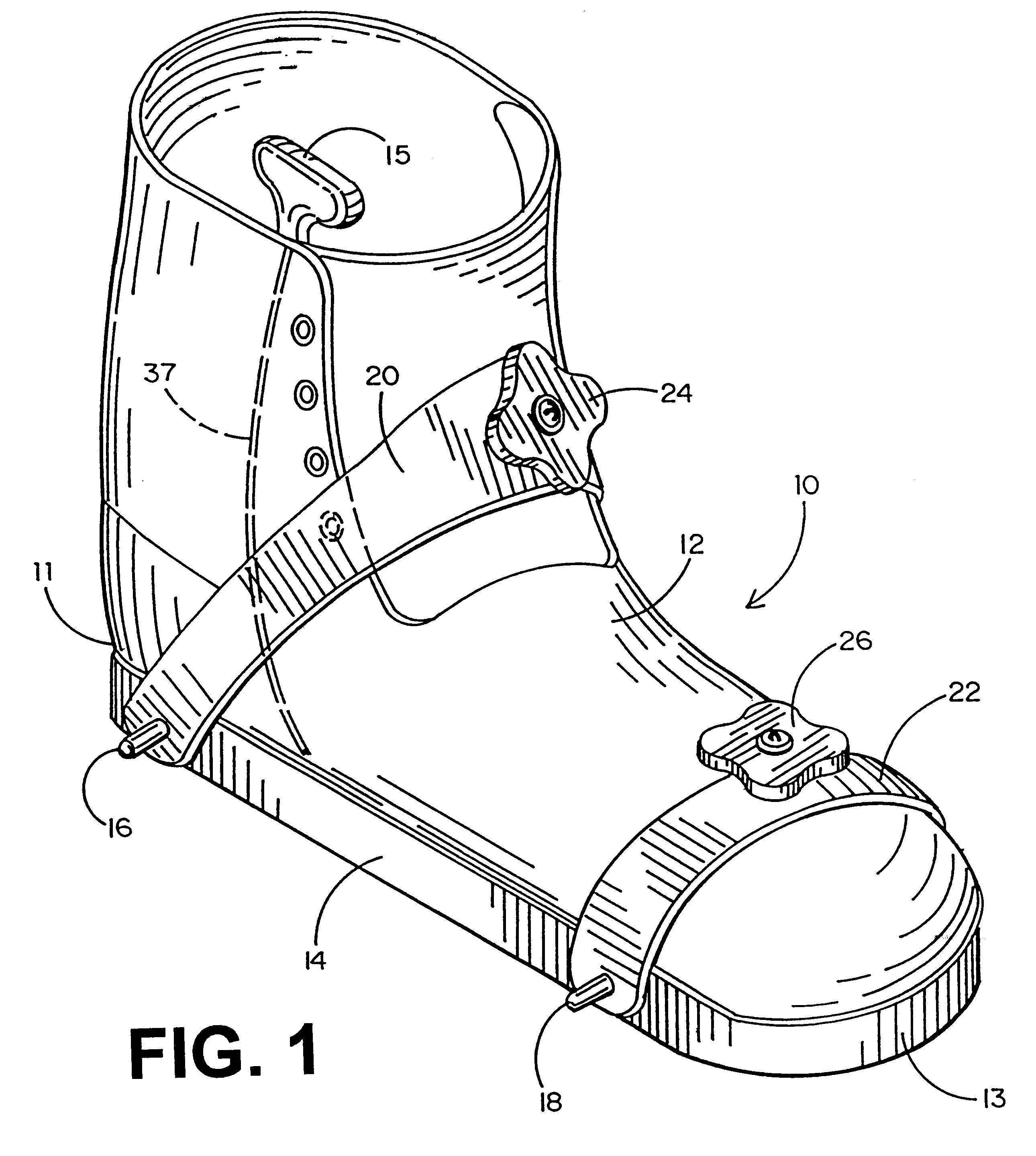
Referring now to the accompanying figures, it will be seen that a snowboard boot 10 of the present invention comprises an upper member 12 and a lower member 14. Four pins 16, 17, 18 and 19, extend laterally from the lower member 14 in a direction which is substantially perpendicular to the length of the boot 10. The pins are located adjacent the heel and toe portions of the boot, but inward from the heel 11 and front 13 of the boot, respectively. The pins are positioned on opposite sides of the lower member 14. Boot 10 also comprises straps 20 and 22 which in the illustrated embodiment, use adjustment knobs 24 and 26, respectively to tighten and loosen the straps in a manner to be disclosed in detail below.
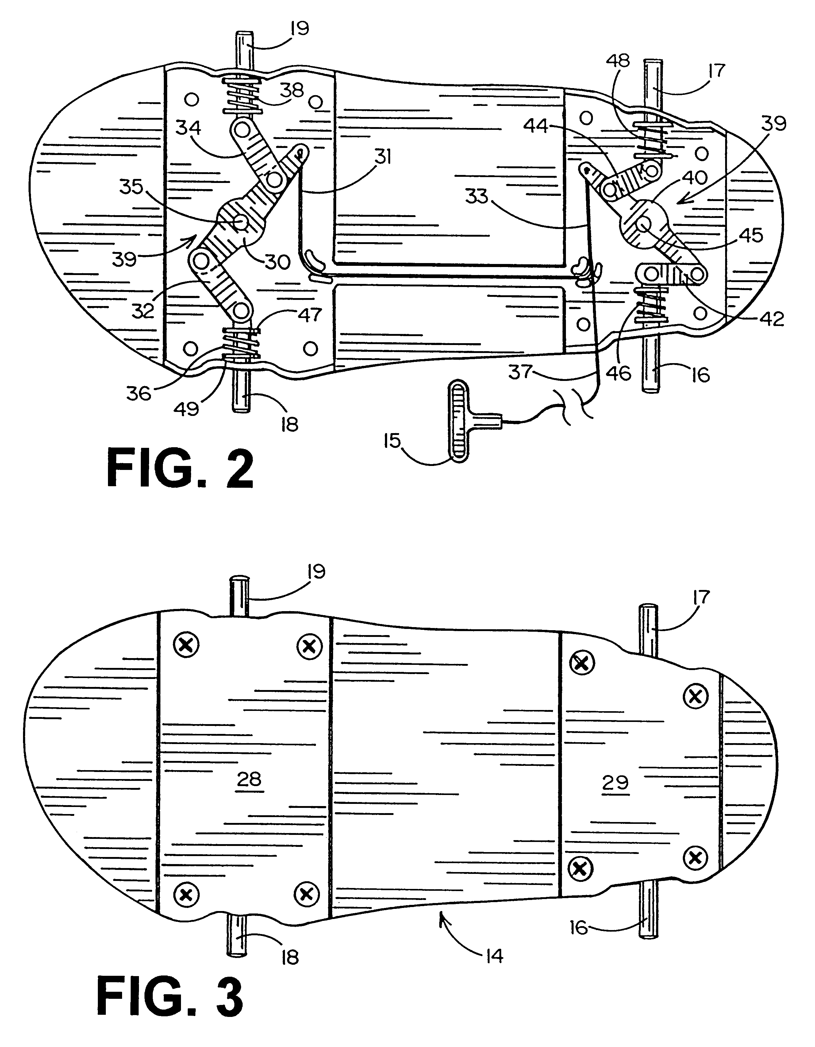
It may be seen in FIGS. 2 and 3 that lower member 14 has a pair of compartments 39, access to which may be obtained by removing covers 28 and 29. Each compartment 39 houses a structure for extending and retracting pins 16, 17, 18 and 19. By way of illustration, pins 18 and 19 are ...
PUM
Abstract
A contact configuration between boot and binding for snowboarding. Contact pins are provided on opposing sides of the boot at both the heel area and the toe area. This 4-point contact configuration assures heel and toe stability and reliable side boot restraint. Concave mating receptacles at matching locations on the binding assure easy and simple interconnection which is also secure and reliable. A release mechanism is provided to selectively retract the pins using a simple pull cord arrangement. Strap linkages permit more convenient tightening and loosening of the boot straps. A strap / yoke configuration provides improved interconnection between the boot and the user's foot. The pull cord is routed within the sole of the boot and upward along the ankle area of the boot for more convenient access. The pull cord is connected to retract linkages at both heel and toe areas, both of those linkages being spring loaded to provide normally extended pins. A variety of pin receptacle configurations are shown for facilitating boot-to-binding step-in connection.
Description
1. Field of the InventionThe present invention pertains generally to the field of snowboarding equipment and more particularly to a new configuration of snowboarding boots and bindings providing convenient grasp and release at distinct points of contact on opposing sides of toes and heels, respectively.2. Prior ArtVarious snowboard binding systems have been disclosed in the prior art. By way of example, U.S. Pat. Nos. 5,190,311; 5,558,355; 4,973,073; 5,577,757; 5,564,719; 5,474,322; 5,505,478; 5,697,631; 4,177,584; 4,205,467; 4,546,524; 5,820,155; 5,695,210; 4,021,056; 5,661,876 and 5,660,410 all disclose snowboard or ski bindings and some disclose compatible boots or shoes. However, all have deficiencies in regard to the interface between the bindings and the boots. More specifically, most of the prior art discloses insufficient contact between boot and binding such as only two points or regions of contact on opposing middle positions of the boot. Such limited contact is inadequate...
Claims
Application Information
Patent Timeline
Application Date:The date an application was filed.
Publication Date:The date a patent or application was officially published.
First Publication Date:The earliest publication date of a patent with the same application number.
Issue Date:Publication date of the patent grant document.
PCT Entry Date:The Entry date of PCT National Phase.
Estimated Expiry Date:The statutory expiry date of a patent right according to the Patent Law, and it is the longest term of protection that the patent right can achieve without the termination of the patent right due to other reasons(Term extension factor has been taken into account ).
Invalid Date:Actual expiry date is based on effective date or publication date of legal transaction data of invalid patent.

