
Lace substitute shoe fastening mechanism

Inactive Publication Date: 2001-09-18
BOWEN RICHARD
View PDF9 Cites 28 Cited by
  • Summary
  • Abstract
  • Description
  • Claims
  • Application Information

AI Technical Summary

Problems solved by technology

Problems inherent in lace closure systems includes unwanted tightening of knots caused by tension in laces occurring through everyday use of shoe, and weakening and eventual breakage of lace at points where lace rubs against eyelets of shoe.
Lace closure systems may also be impractical and undesirable by persons with rheumatoid arthritis, or persons with weight problems, or injuries which make it difficult for them to bend over for the period of time required to perform lace closure.
U.S. Pat. No. fastening of a shoe but employs use of many small moving parts which increases the risk of something going wrong rendering the device useless.

Method used


Image

  • Lace substitute shoe fastening mechanism
  • Lace substitute shoe fastening mechanism
  • Lace substitute shoe fastening mechanism

Examples


first embodiment

the invention is exactly the fstening device portion of U.S. Pat. No. 6,018,890, and operates in the manner described herein.

DESCRIPTION OF SECOND AND THIRD EMBODIMENTS

second embodiment

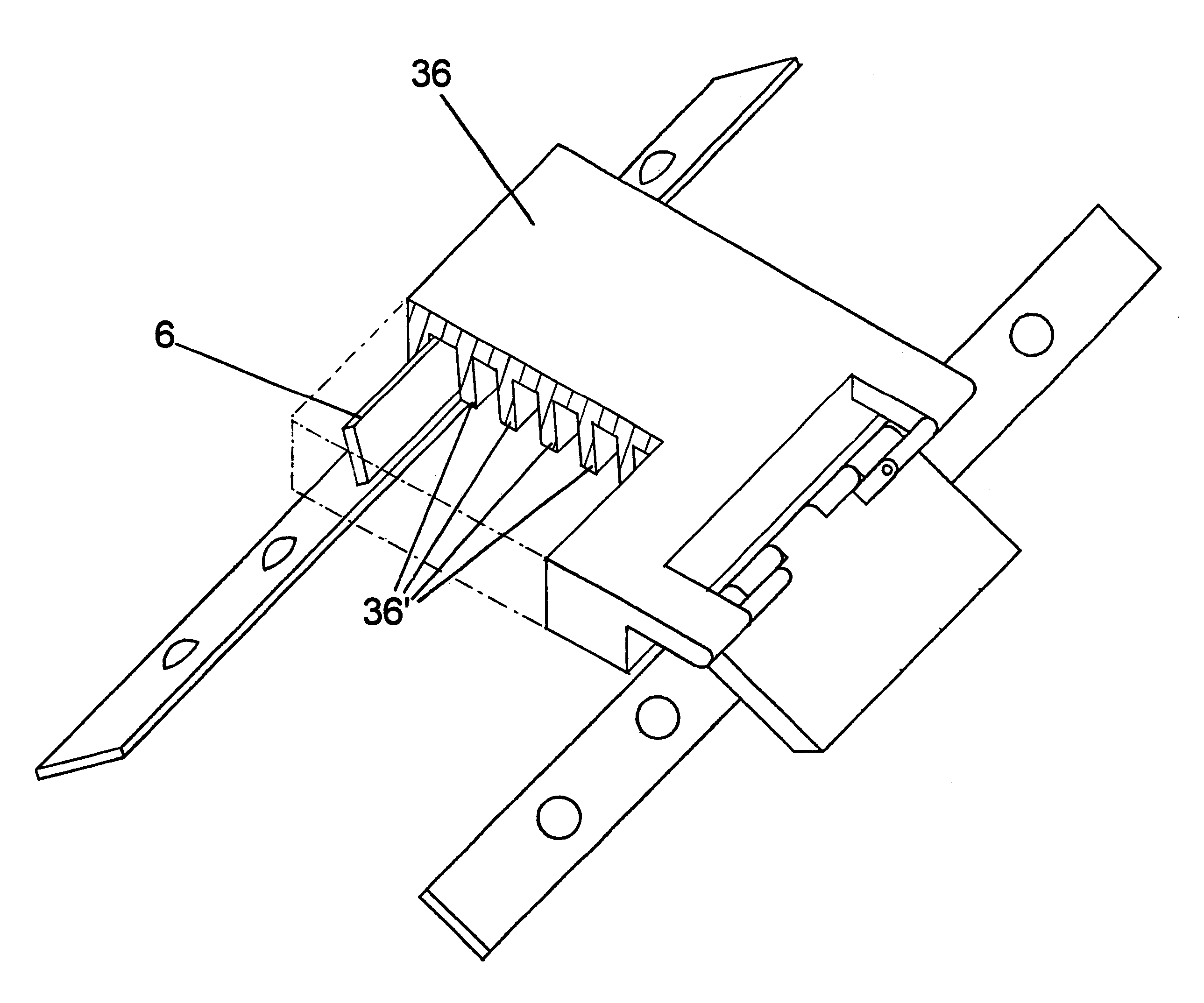
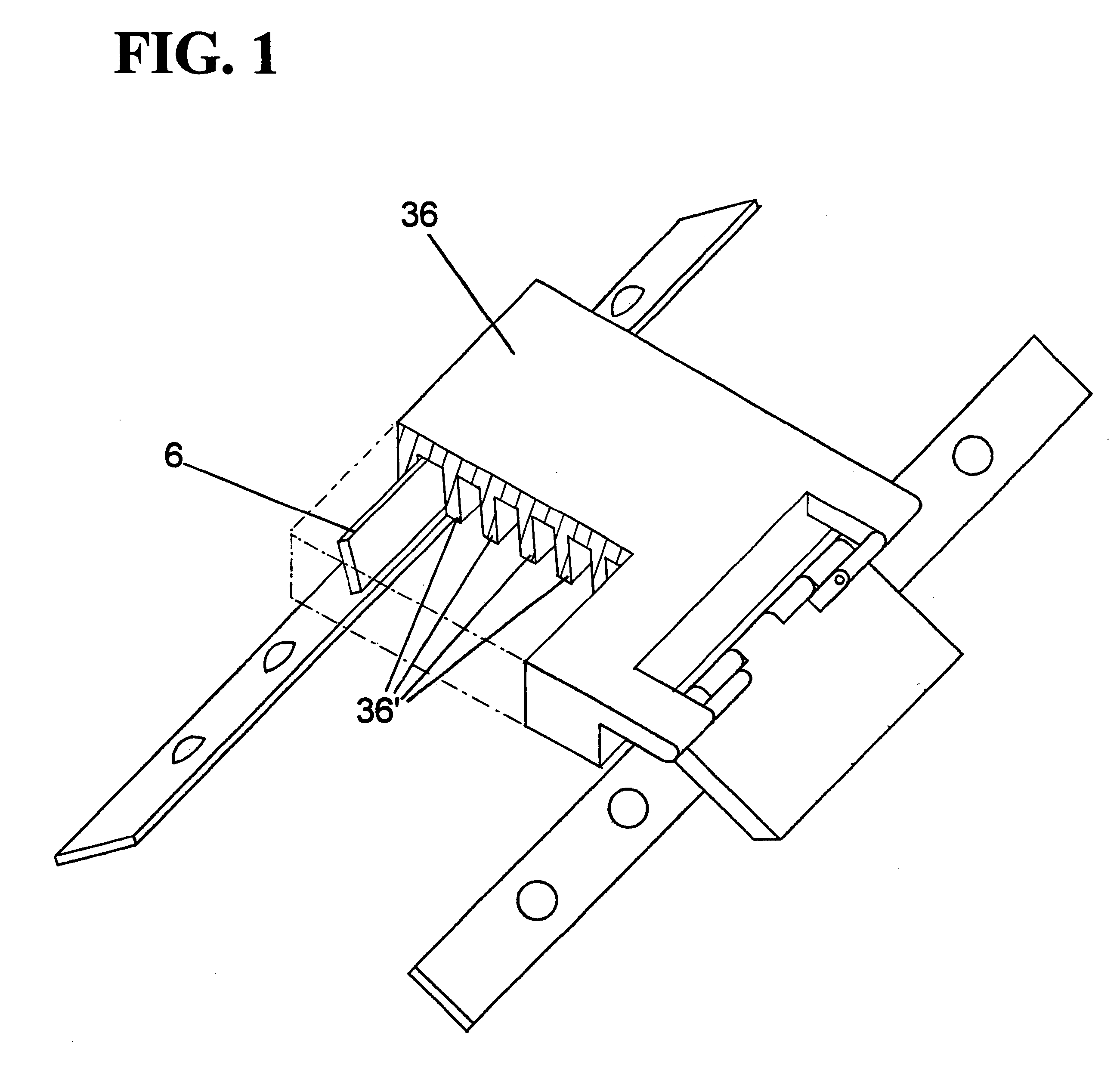
the invention as seen in FIG. 7 is similar to the first embodiment in all respects except for the tie element. Reviewing FIG. 7 the tie element 36 of this embodiment comprises a singular and substantially rectangular component defining a substantially planar undersurface from which a series hook elements 36' project. Each of the hook elements is engageable with the catch element 6.

third embodiment

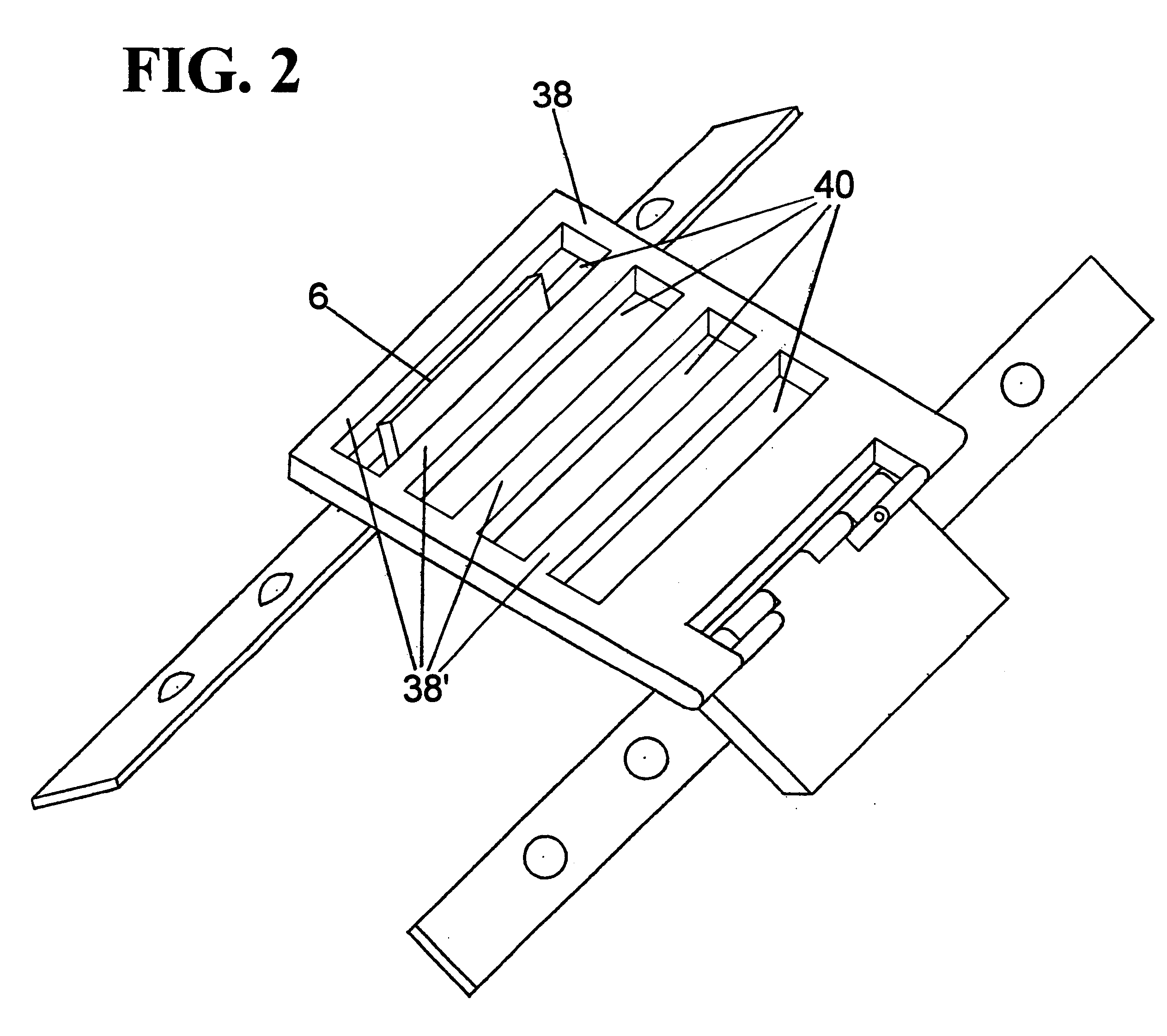
the invention as seen in FIGS. 2, 3A, and 3B is similar to the first and second embodiments in all respects again except for the tie element. The tie element 38 of this embodiment is a singular and substantially planar component comprising a series of longitudinal surface to surface apertures 40 located through its cross-section and a series of rung like elements 38' where each rung like element is followed by an aperture and each aperture is followed by a rung like element and so on in an alternating fashion. Each rung like element 38' is engageable with the catch element 6.

DESCRIPTION OF OPERATION OF SECOND AND THIRD EMBODIMENTS

The second and third embodiments of the invention each operate in a manner similar to that of the first embodiment so that when downward rotatable force is applied to the actuating lever and the tie element retracts, just as interrengagement of the hook element and catch element occurs in the first embodiment in U.S. Pat. No. 6,018,890 there is an interenga...


PUM


Abstract

A continuation in part of U.S. Pat. No. 6,018,890 the fastener device portion of the patent. Another version of the fastening device comprises an actuating lever rotatably secured to one flap of a shoe and where hinged onto actuating lever is a tie element extending substantially in alignment therewith, and comprising a substantially planar undersurface with a series of hook element projecting therefrom where any of the hook elements are engageable with a catch element secured to the opposing flap of shoe. Another version of the device has a tie element comprising a substantially planar and rectangular component defining a series of rung like members where each rung like member is engageable to said catch element. Like the first embodiment described in U.S. Pat. No. 6,018,890 upon rotation of the actuating lever towards the opposing flap the tie element translates laterally towards and beyond catch element, and upon rotating of actuating lever away from opposing flap the tie element translates laterally away from catch element causing engagement between the catch element and any of the said hook elements or between catch element and any of the said rung like members. Ramifications of the device include multiple axle support heating assemblages, bearing assemblages, repositionable on bearing mount via detachable and interfitting engagement of recesses and protrusion located on an undersurface of bearing assemblage with corresponding recesses and protrusions located on bearing mount, and hearing assemblages and catch element secured to their respective mounts via swivel means.

Description

A continuation in part of U.S. Pat. No. 6,018,890 provides a shoe fastening device employing use of a hand actuated lever which is attached to one flap of a shoe, a tie element pivotally attached to said lever and which acts as an extension of lever, and where one tie element is exactly described in abovementioned patent. Another having a series of hook elements projecting from an undersurface, and another version having a series of rung like members, and where either a hook element or a rung like member engages a catch element secured to the opposing flap of shoe, and with ramifications to the device including multi axle support bearing assemblages, bearing assemblages repositionable on bearing mount, and bearing assemblages and catch element swivel capable.1. Field of InventionThis invention is related to the field of shoe securing and fastening devices, and pertains more particularly to a lace substitute for conventional shoes constructed with duel flaps on opposing sides of a to...

Claims


Application Information

Patent Timeline
IPC IPC(8): A43C11/14A43C11/00
CPCA43C11/1453Y10T292/42
Inventor BOWEN, RICHARD
Owner BOWEN RICHARD
Learn More