Rotary press

a rotary press and rotary press technology, applied in the field of rotary presses, can solve the problems of increasing paper spoilage, preventing the improvement of print quality, and the water transfer roller of the conventional rotary press,

Inactive Publication Date: 2001-10-09
TOSHIBA MASCH CO LTD
View PDF3 Cites 48 Cited by
  • Summary
  • Abstract
  • Description
  • Claims
  • Application Information

AI Technical Summary

Problems solved by technology

However, following disadvantages occur in driving the ink transferring rollers and the water transferring rollers of the conventional rotary press.
Accordingly, doubling and hickey, which can be prevented by changing the peripheral speed, are likely to be caused, thereby preventing the print quality from being improved.
Therefore, extra web W is used before generating the ink film and the emulsified status, which increases paper spoilage.
Consequently, the web W has to be inserted between the blanket cylinders, which is troublesome and deteriorates efficiency of printing process since the clutch has to be set on and off to deteriorate operability.
On the other hand, in printing on a rough paper etc., paper dust or the like may be raised when there is a peripheral speed difference and the paper dust is likely to adhere on the surface of the water form roller, thereby hindering printing with good quality.
However, since the water transferring rollers 67 cannot be driven with variable speed in the conventional drive, the peripheral speed of the water rollers cannot be changed freely in accordance with the paper.
Accordingly, it is difficult to print on printing papers having different paper quality (e.g. coated paper and rough paper), thereby hindering improvement of printing quality.
The above problems occur because the rollers are mechanically driven.
In the above arrangement, however, control accuracy is difficult to be obtained because of being general-type proportional operation method, so that speed fluctuation unevenness is likely to be caused on account of touch shock of the ink fountain roller and a shock by a gap of the print cylinder, thereby being difficult to keep the peripheral speed relative to the print cylinder surface.
Accordingly, water pattern and ink pattern are likely to be generated on the printing paper, thereby deteriorating print quality.
Further, in order to exclude such rotational speed unevenness, inertia on the motor side and output torque have to be made larger for enduring momentary torque fluctuation, which requires large-capacity motor, thereby obstructing reduction of size of the unit and cost.

Method used


Image

  • Rotary press
  • Rotary press
  • Rotary press

Examples


Embodiment Construction

)

An embodiment of the present invention will be described below with reference to attached drawings.

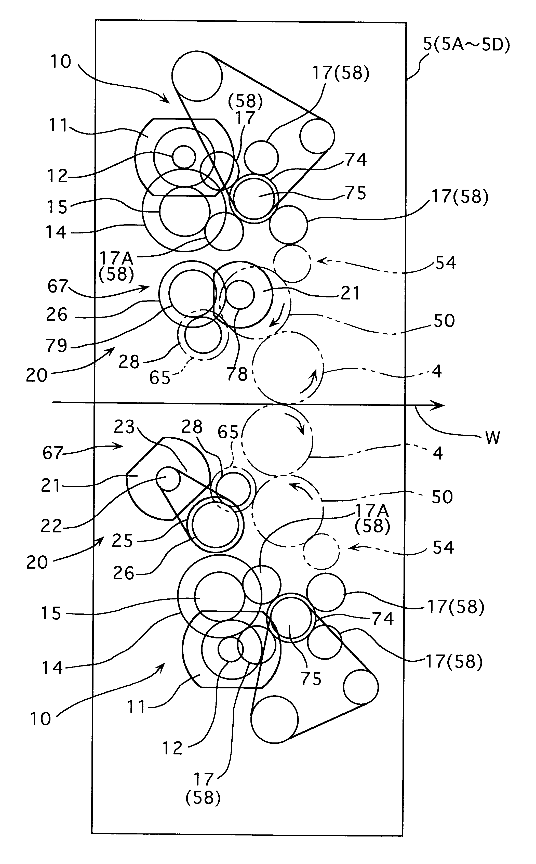
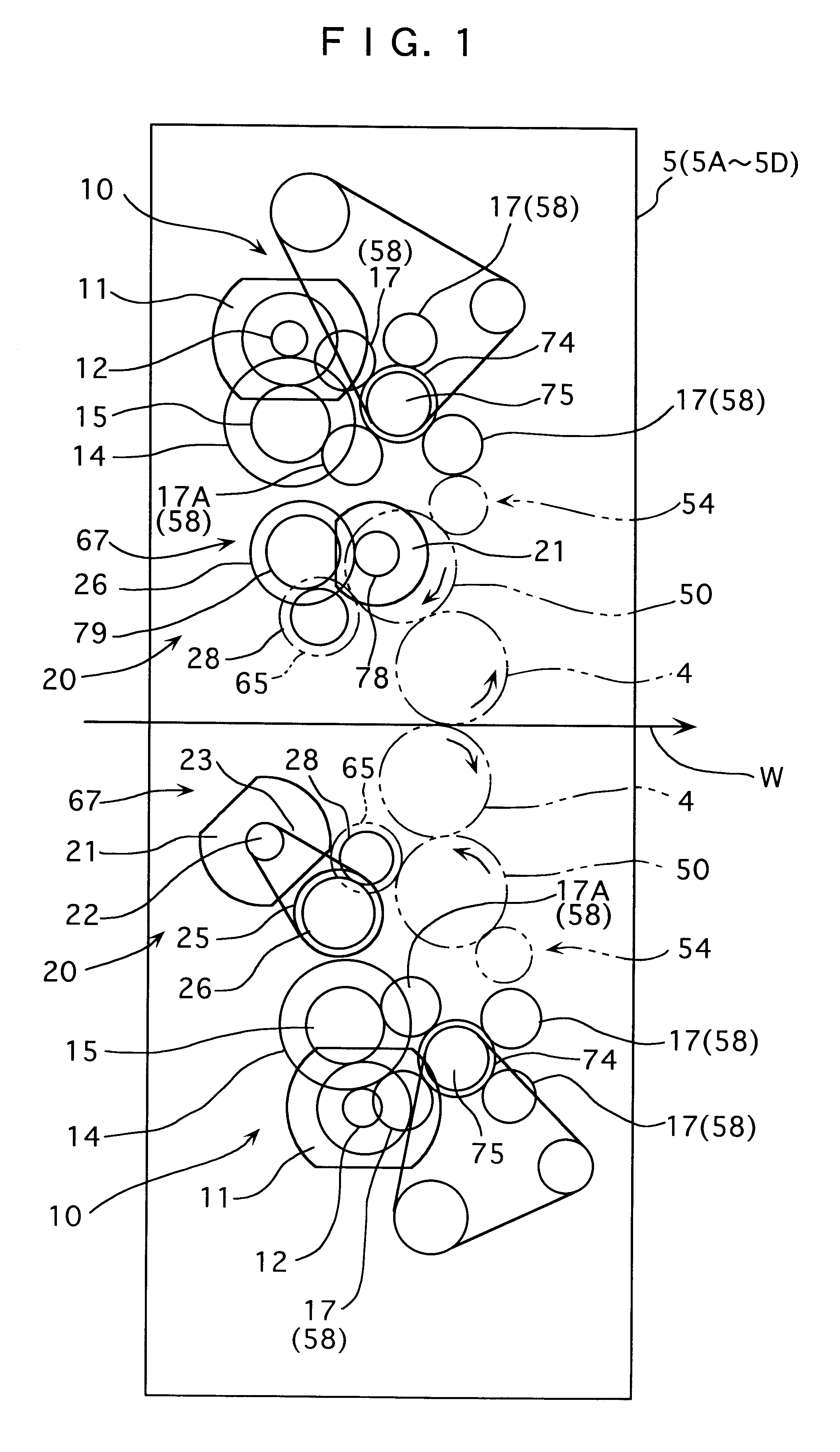
As shown in FIG. 1, the ink transferring rollers 54 and the water transferring rollers 67 provided on the printing unit 5A according to the present embodiment are capable of independently being driven respectively by an ink transferring rollers driving unit 10 and a water transferring rollers driving unit 20.

Incidentally, the ink transferring rollers and the water transferring rollers of the present embodiment are corresponding to the ink transferring rollers 54 and the water transferring rollers 67 of the conventional printing unit 5A. The same reference numeral is attached to the same arrangement and members used as the conventional printing unit 5A to omit or simplify detailed explanation therefor.

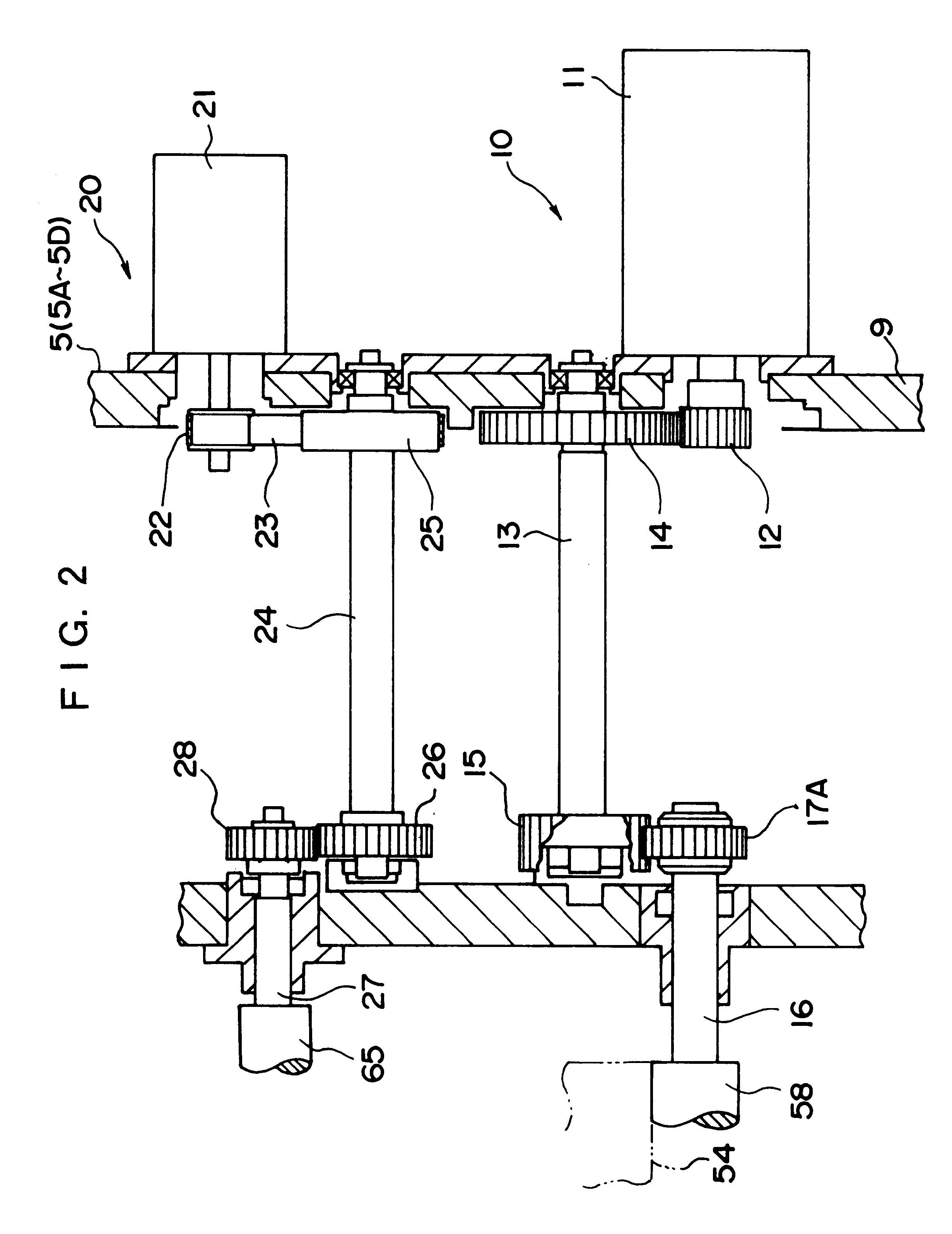
As shown in FIG. 2 (FIG. 2 shows only lower side of the printing unit), the ink transferring rollers driving unit 10 has an ink form roller driving motor 11 (referred to as ink motor here...


PUM


Abstract

In a rotary press, ink transferring rollers and water transferring rollers provided in printing units are capable of separately and speed-variably controlled respectively by ink transferring rollers driving unit and water transferring driving unit independently of drive of print cylinder of the printing unit. Accordingly, spoilage can be avoided and printing failure such as doubling and hickey can be prevented, thereby improving print quality.

Description

1. Field of the InventionThe present invention relates to a rotary press having a printing unit for printing picture on a web fed by a paper feeder.2. Description of Related ArtAs shown in FIG. 4, a general offset rotary press 1 has a paper feeder 2 for feeding consecutive web W, a delivery device 3 for delivering the web W from the paper feeder 2 to downstream (in right direction in the figure), a printer 5 including a plurality of printing unit 5A to 5D having blanket cylinder 4 etc. thereinside for printing picture on the web W delivered by the delivery device 3, a drier 6 for drying ink distributed on the printed web W, a cooler 7 for cooling the web W sent from the drier 6, and a folding machine 8 for cutting and folding the web W.As shown in FIG. 5, the respective printing units 5A to 5D (represented by the printing unit 5A hereinafter) of the rotary press 1 include a print cylinder 50 having printing form, the blanket cylinder 4 for printing on the web W by being transferred ...

Claims


Application Information

Patent Timeline
Patent Type & Authority Patents(United States)
IPC IPC(8): B41F31/00B41F13/00B41F31/14B41F33/10
CPCB41F31/004
Inventor GOTANDA, TAKASHIKAWAGUCHI, TAKAFUMI
Owner TOSHIBA MASCH CO LTD
Why Eureka
Try Eureka