Shield fixing structure in helmet

a technology for fixing structures and shields, applied in the direction of helmets, protective garments, hats, etc., can solve the problems of damage to the engaging members formed at the shield pressing cover, the shield cannot be fixed or disengaged, and the screws used in fixing the shield pressing cover are los

Inactive Publication Date: 2001-10-16
ARAI MICHIO
View PDF13 Cites 28 Cited by
  • Summary
  • Abstract
  • Description
  • Claims
  • Application Information

AI Technical Summary

Problems solved by technology

Under this invention, all the disadvantages that the shield could not be fixed or disengaged unless the shield pressing cover was removed, i.e. disadvantages that the screws for use in fixing the shield pressing cover are lost or the engaging members formed at the shield pressing covers are damaged have been resolved.
However, i

Method used


Image

  • Shield fixing structure in helmet
  • Shield fixing structure in helmet
  • Shield fixing structure in helmet

Examples


Embodiment Construction

)

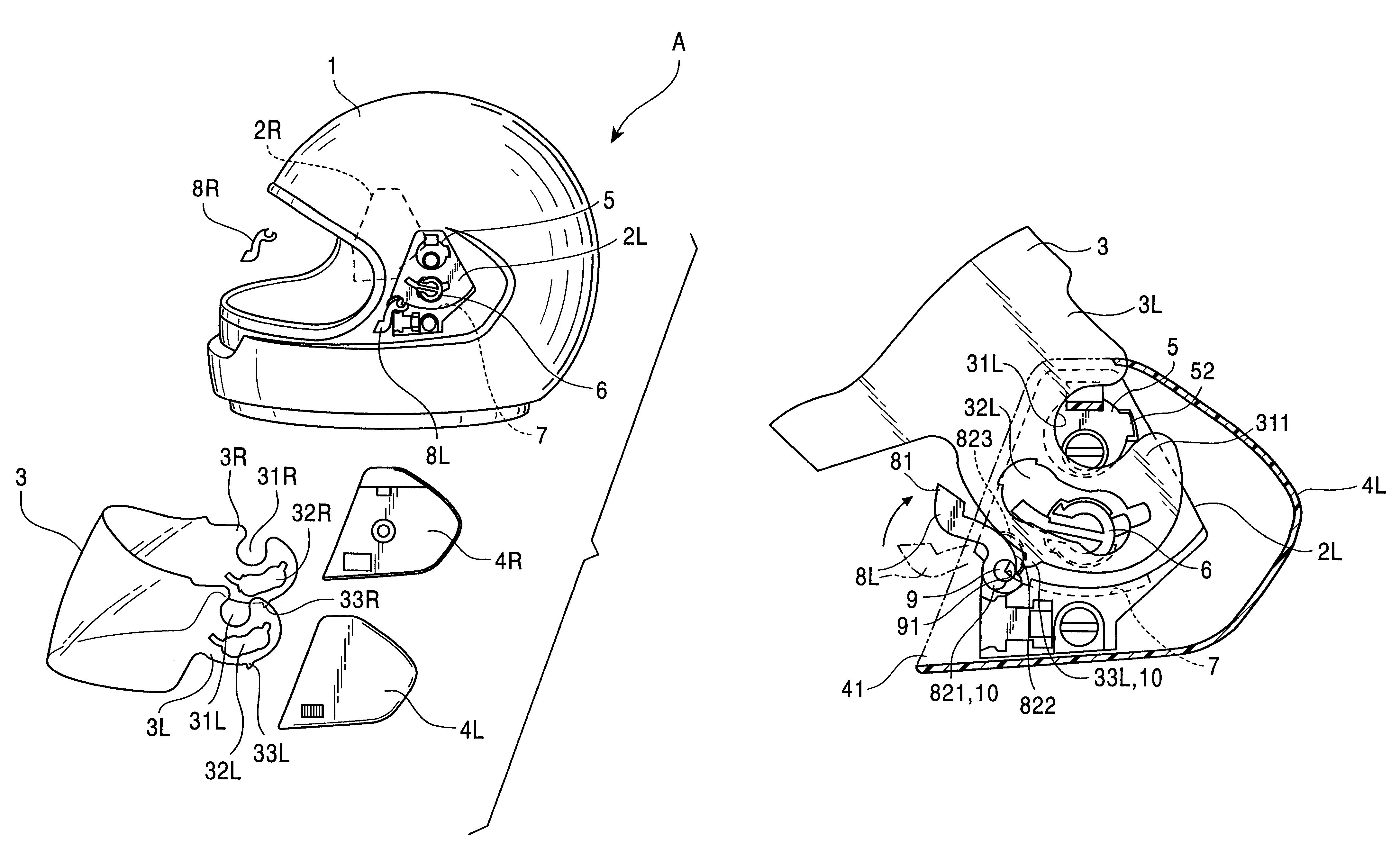
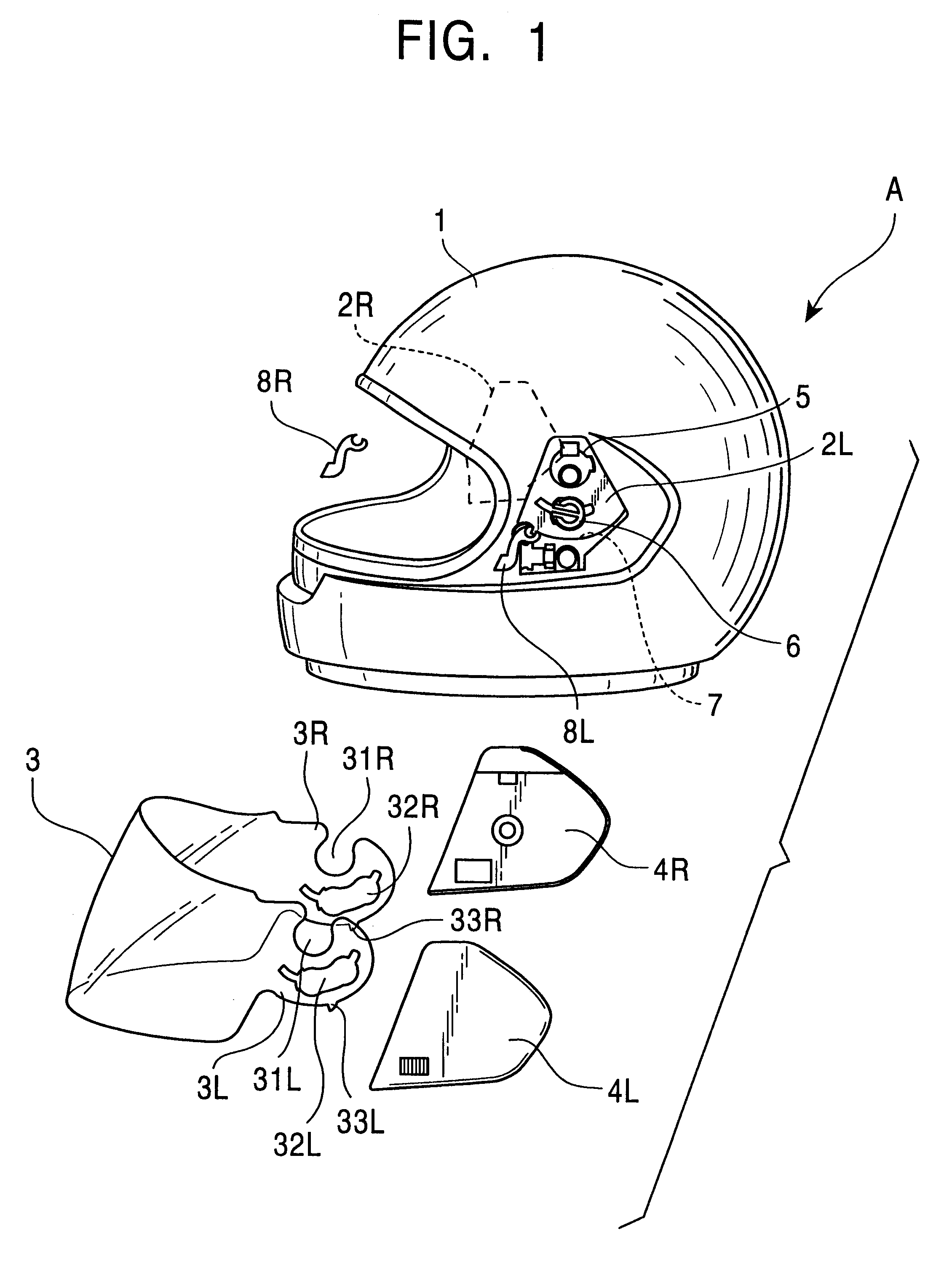
Referring now to the drawings, some preferred embodiments of the present invention will be described as follows, wherein FIG. 1 shows a full-face helmet A to which the fixing structure of the present invention is applied and it shows an example in which operating levers 8L, 8R of rotating operation type are provided. In this figure, 1 denotes a main body of the helmet, 2L, 2R denote base plates fixed to the right and left outer surfaces of the main body 1 of the helmet, 3 denotes a shield, and 4L, 4R denote shield pressing covers. Since the operating levers 8L, 8R, the base plates 2L, 2R and the shield pressing covers 4L, 4R have the same form at their right and left sections, only the operating lever 8L, base plate 2L, shield pressing cover 4L and their associated portions will be described later.

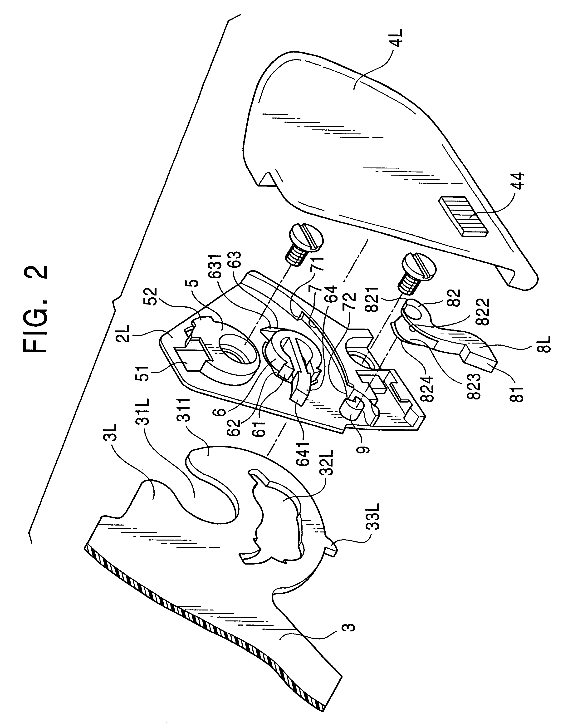
The base plate 2L has a supporting shaft 5 acting as a rotating center of the shield 3, a resilient engaging piece 6 for restricting a rotating range of the shield 3 and applying a certai...


PUM


Abstract

The object of the invention is to improve an easiness in removing operation of a shield. The operating lever is rotated or slid to push wide the shield pressing cover in an outward direction, a clearance through which the shield can pass is formed between the shield pressing cover and the top point of the supporting shaft, the fixing section of the shield is reached to the top point of the supporting shaft, thereby the shield can be easily removed.

Description

1. Field of the InventionThis invention relates to a shield fixing structure which is installed in a full-face type helmet and an open face type helmet which a driver wears helmet when he or she rides on various kinds of motorized vehicles such as motorcycle, automobile or others.2. Description of the Prior ArtAs Japanese Patent Publication No. Hei 6-89483, the present applicant has filed as a proposal a fixing structure in which a shield can be fixed or disengaged without removing the shield pressing cover. Under this invention, all the disadvantages that the shield could not be fixed or disengaged unless the shield pressing cover was removed, i.e. disadvantages that the screws for use in fixing the shield pressing cover are lost or the engaging members formed at the shield pressing covers are damaged have been resolved.However, the fixing structure in the aforesaid invention is operated such that after the shield is rotated up to its upper limit position, the portion near the shie...

Claims


Application Information

Patent Timeline
IPC IPC(8): A42B3/22A42B3/18
CPCA42B3/222
Inventor ARAI, MICHIO
Owner ARAI MICHIO
Why Eureka
Try Eureka