

Corner shower seat
a shower seat and corner technology, applied in baths, bath covers/linings, constructions, etc., can solve the problem of limited horizontal marble slab installation of the disclosed shower sea
- Summary
- Abstract
- Description
- Claims
- Application Information
AI Technical Summary
Problems solved by technology
Method used
Image

Examples
Embodiment Construction
A corner shower seat constructed of a rigid material in a shower stall is disclosed.
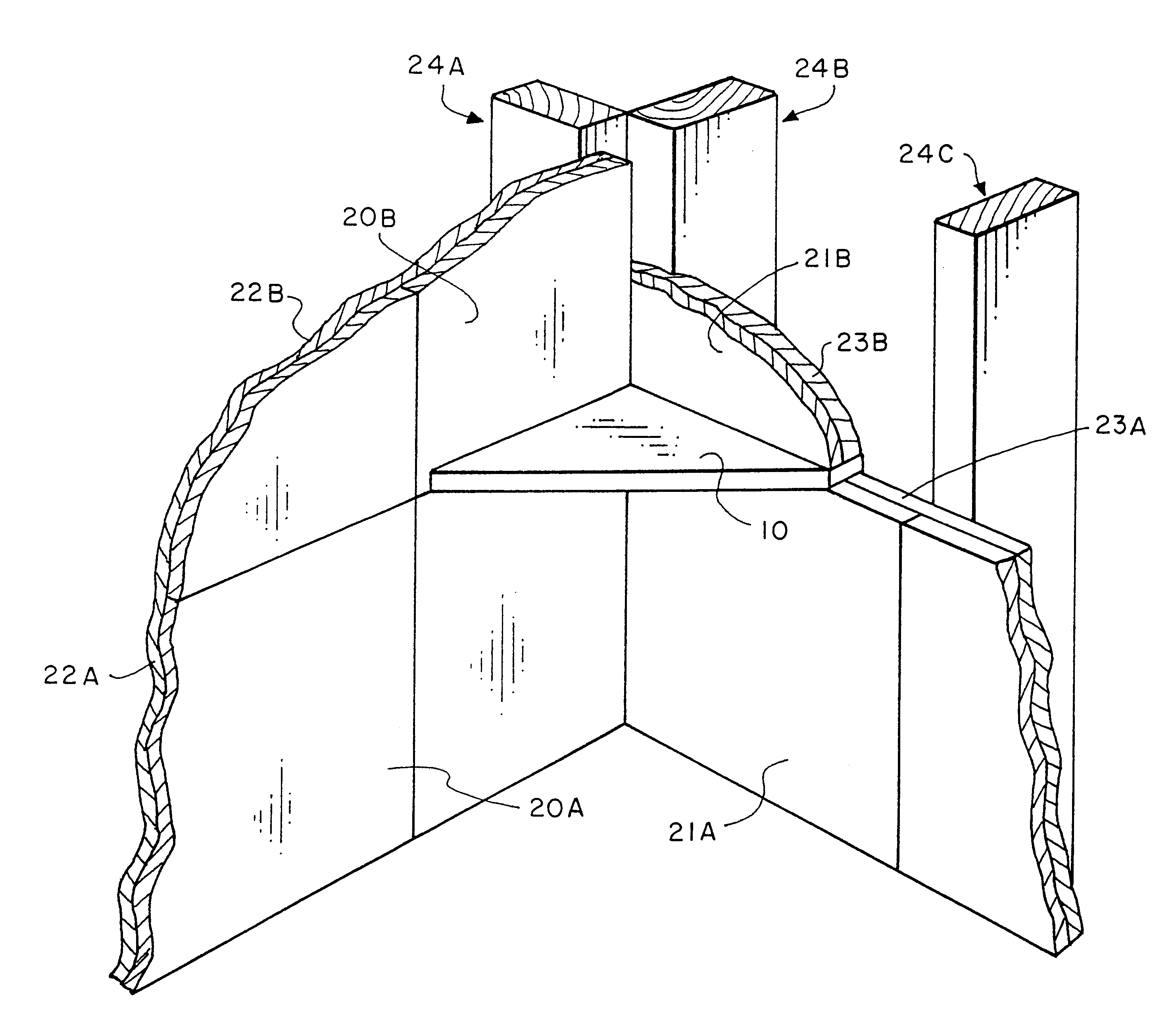
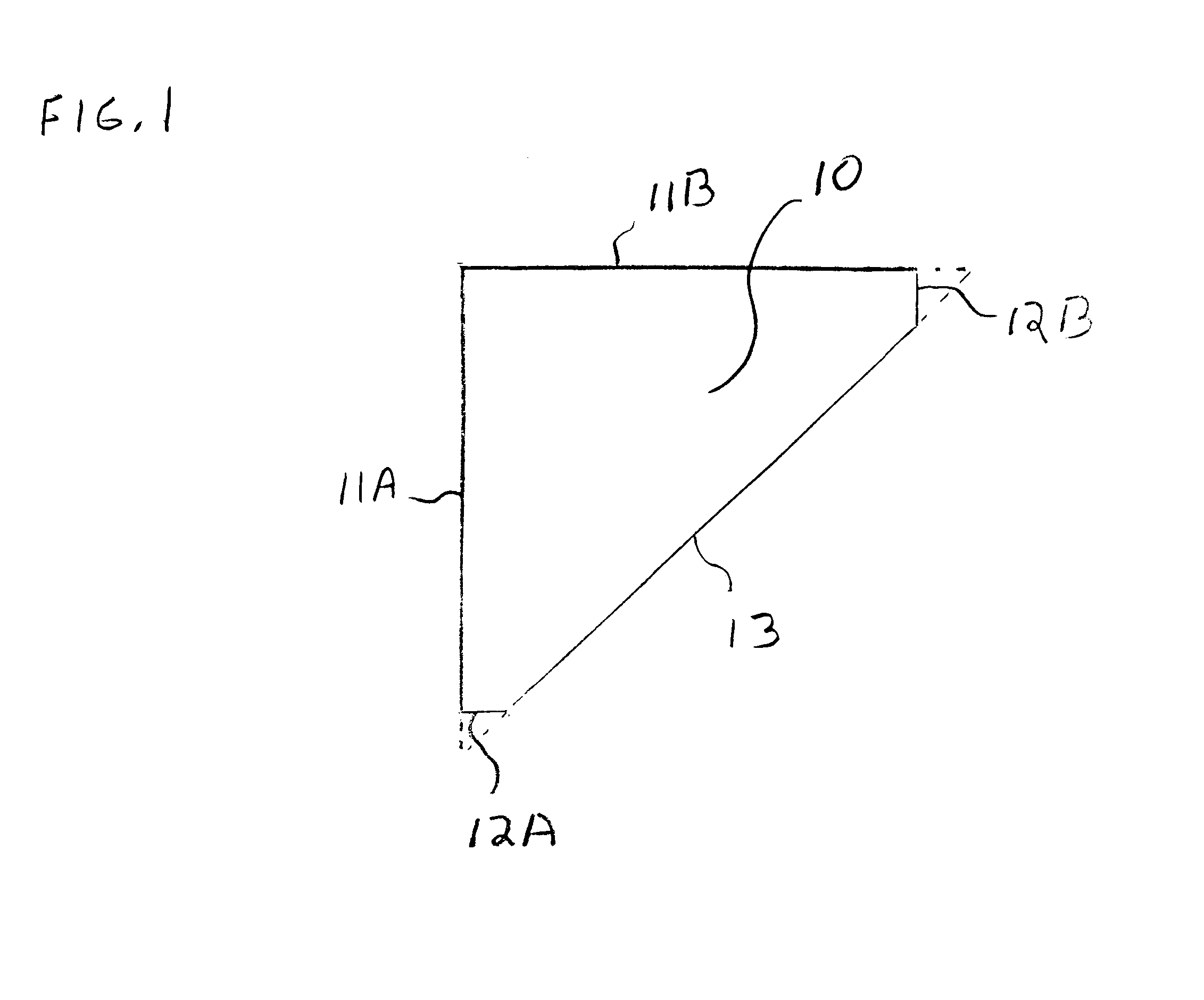
FIG. 1 is a top plan view of a horizontal slab 10 in the preferred embodiment of the present invention. Preferably, the shower seat is polygonal in shape and constructed of cultured marble having a thickness of at least 3 / 4 of an inch. However, the horizontal slab may be made of any rigid material able to hold the weight of a person, such as natural stone, plastic, concrete, fiberglass, or any ceramic. In the preferred embodiment, the slab 10 includes edges 11A, 11B, 12A, 12B, and 13.
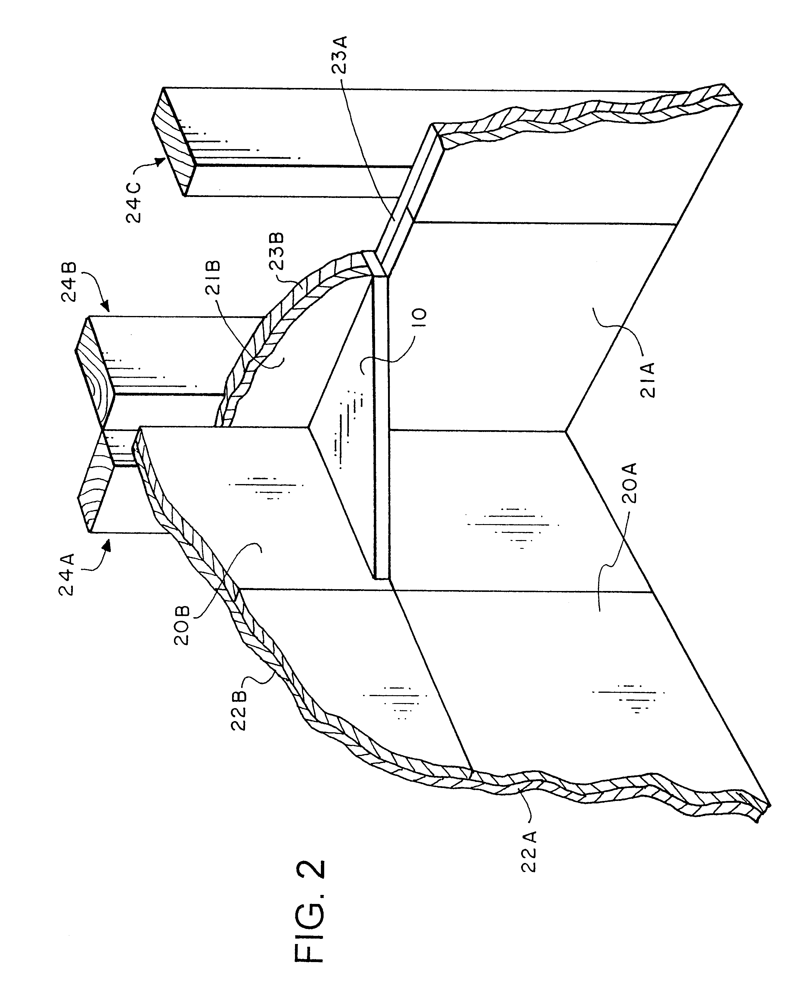
FIG. 2 illustrates the slab 10 of FIG. 1 installed within a corner of a shower stall in the preferred embodiment of the present invention. Exterior wall material 20A, 20B, 21A, and 21B are constructed of a waterproof material such as marble, ceramic tile, natural stone, fiberglass, plastic, or granite. Directly behind and in contact with the exterior wall material is backboard material 22A, 22B, 23A, and 23B.
The backboar...
PUM
 Abstract
Description
Claims
Application Information