Vehicle seat having a pivot mechanism

a technology of pivot mechanism and seat, which is applied in the direction of vehicle parts, chairs, vehicle arrangements, etc., can solve the problem that the movement of nuts is not compatible with providing a simple mechanical connection, and achieve the effect of simple mechanical connection

Inactive Publication Date: 2001-11-20
BERTRAND FAURE EQUIP SA (FR)
View PDF9 Cites 26 Cited by
  • Summary
  • Abstract
  • Description
  • Claims
  • Application Information

AI Technical Summary

Benefits of technology

As a result of these features, a simple, mechanical connection can be provided between the electric motor and the part of t...

Problems solved by technology

However, electrical operation of a pivot mechanism of this type gives rise to a problem if it is desirable to mount the electric motor activating the pivot mechanism on the first part of the s...

Method used


Image

  • Vehicle seat having a pivot mechanism
  • Vehicle seat having a pivot mechanism
  • Vehicle seat having a pivot mechanism

Examples


Embodiment Construction

The same references are used in the different drawings to denote identical or similar elements.

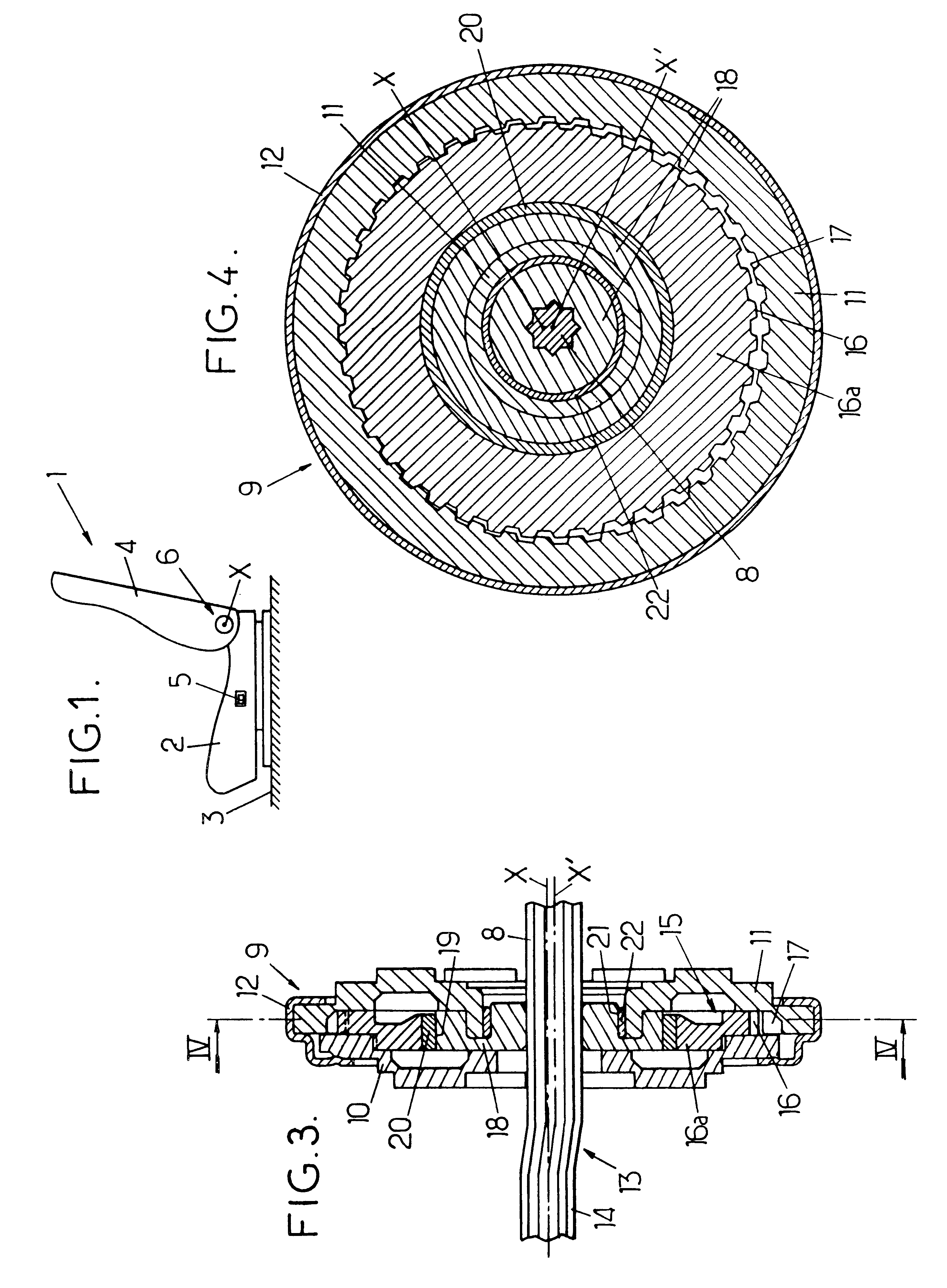
FIG. 1 illustrates a front seat 1 of a motor vehicle which has, on the one hand a seat 2 mounted on the floor 3 of the vehicle and on the other a backrest 4 which is mounted so as to pivot on the seat about a horizontal transverse axis X.

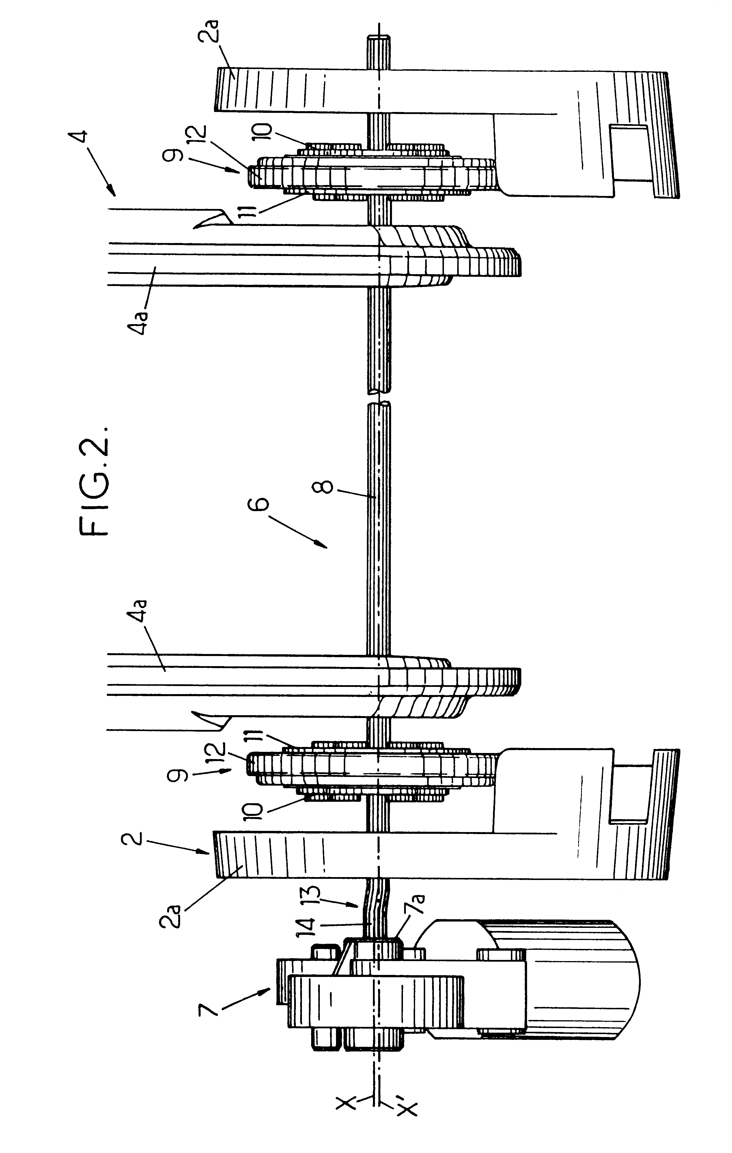
The inclination of the backrest 4 can be adjusted by means of an electric button 5 which controls a device for adjusting the inclination 6 comprising an electric gear motor 7 illustrated in FIG. 2.

The gear motor 7 drives a horizontal transverse splined control shaft 8 in rotation, which in turn controls two identical pivot mechanisms 9 arranged at either side of the seat.

Each pivot mechanism 9 comprises a single-train hypocycloid gear mechanism which will be described in more detail below and which, in the particular example discussed here, is contained in a closed circular housing consisting of:

a disc-shaped mobile metal flange 10 which extends perpendicu...


PUM


Abstract

A vehicle seat comprises a backrest mounted on a seat by means of a pivot mechanism comprising two flanges fixed respectively to the seat and the backrest and linked one to the other by means of a single-train hypocycloid gear mechanism which causes the backrest to pivot about an axis of rotation which in turn moves in circular translation about a fixed axis. The gear mechanism is driven by a control shaft which is centered on the axis of rotation on a level with said gear mechanism and which has a part forming a crank comprising an end centered on the fixed axis, which end is driven in rotation by an electric motor mounted on the seat part.

Description

The present invention relates to vehicle seats having pivot mechanisms.More specifically, the invention relates to a vehicle seat having first and second parts mounted so as to pivot relative to one another by means of a first pivot mechanism comprising:a single-train hypocycloid gear mechanism, this gear mechanism comprising first and second annular toothed gears meshing one with the other and joined respectively to the first and second parts of the seat, the first and second sets of teeth being arranged so that one extends radially towards the exterior and the other radially towards the interior and said first and second teeth respectively have first and second transverse horizontal central axes, offset one from the other,a cam mounted so as to rotate on the one hand relative to the first set of teeth about the first axis and on the other relative to the second set of teeth about the second axis in order to drive the first and second sets of teeth in relative rotation,and a contro...

Claims


Application Information

Patent Timeline
IPC IPC(8): B60N2/225A47C1/025
CPCB60N2/2252
Inventor LEVERT, EMMANUELLEPAULE, FRANCK
Owner BERTRAND FAURE EQUIP SA (FR)
Why Eureka
Try Eureka