Resin forming optical lens

An optical lens and resin molding technology, applied in optics, lenses, optical components, etc., can solve problems that are difficult to realize, hinder application and introduction, and achieve the effect of simplifying the assembly process and reducing the concentration loss

Inactive Publication Date: 2010-10-27
NIPPON CERAMIC CO LTD
View PDF2 Cites 0 Cited by
  • Summary
  • Abstract
  • Description
  • Claims
  • Application Information

AI Technical Summary

Problems solved by technology

[0008] The problem point to be solved by the present invention is: for example Figure 8 The shown optical lens 3b, which is directly mounted and supported on the pyroelectric infrared detector 5, is conventionally formed as an injection-molded product made of a high-density polyethylene material having excellent infrared transmittance, and the lens part 1 and the support part 2 are formed as One-piece type, but due to the structure of the injection molding mold and the conditions for forming the mold, the maximum external dimension of the condensing lens part 1 located on the upper side is larger than the maximum external dimension of the support part 2 mounted on the pyroelectric infrared detector. The structure of the support part is difficult to realize in the integral type formation of injection molding
[0009] Therefore, in constructing an infrared detection system having an optical lens (a multi-concentration type condenser lens composed of a convex body or a Fresnel shape body), for example, a plurality of small lens parts that subdivide the infrared detection area of ​​the detection object surface are densely arranged. In the case of a device, generally in order to maintain the infrared detection performance, it is necessary to expand the area of ​​the above-mentioned small lens with a plurality of arrangements to receive more infrared light in the detection target area, resulting in the following problems: For example, when using TO For -5 type pyroelectric infrared detectors, it is necessary to adopt a design in which the shape and size of the optical lens part itself is larger than the packaging size of the detector case.
In other words, this means that in the integral injection molding, the size of the fixed support part of the optical lens is larger than the package periphery of the pyroelectric infrared detector to be mounted, and it is difficult to form an installation structure in which the lens support part can be directly held on the pyroelectric infrared detector.
This hinders the application and introduction of a simplified assembly process for directly mounting the optical lens on the pyroelectric infrared detector as a method of mounting it on the infrared detection device. Fixed area of ​​the above optical lens

Method used


Image

  • Resin forming optical lens
  • Resin forming optical lens
  • Resin forming optical lens

Examples


Embodiment 1

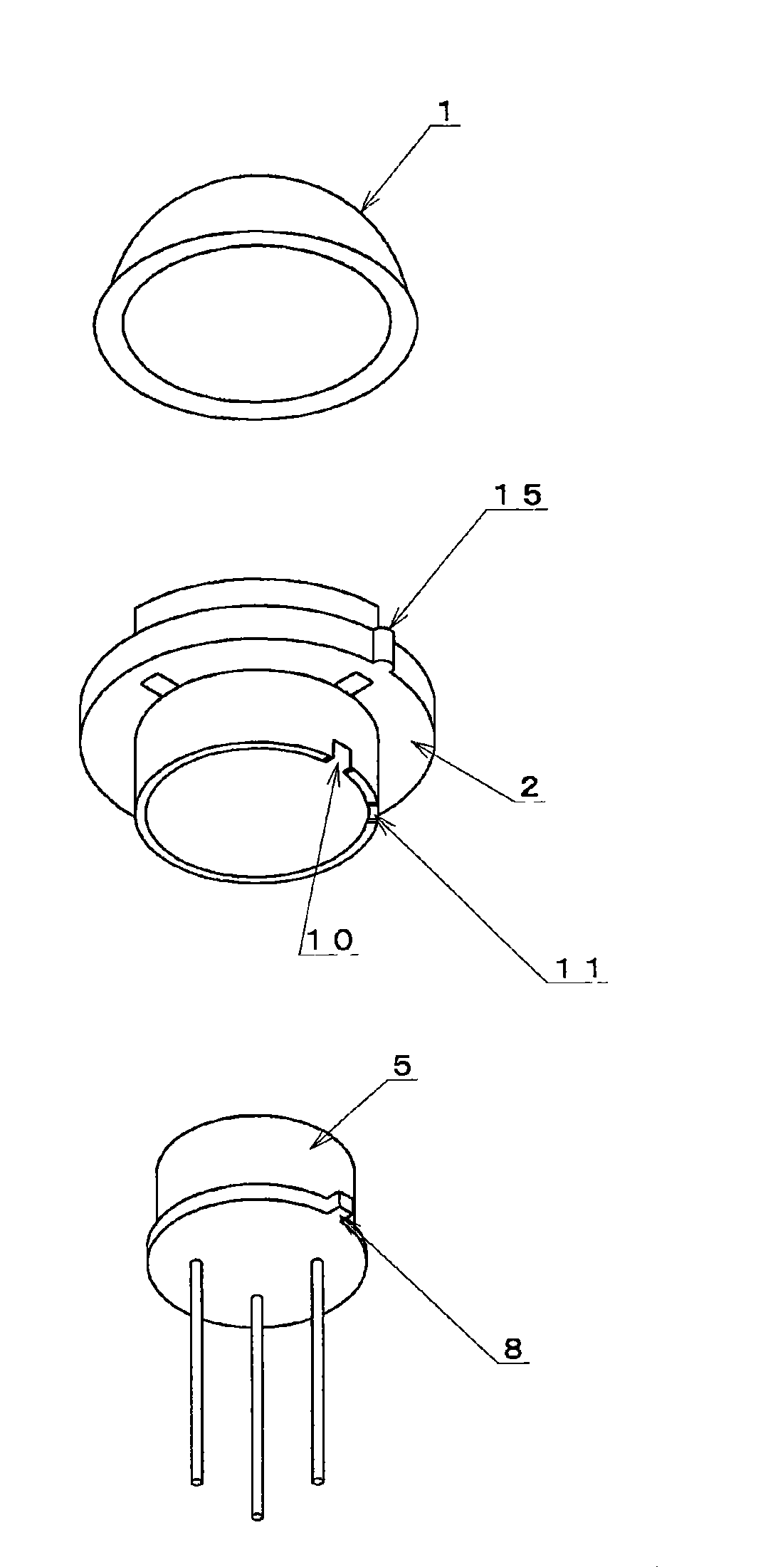
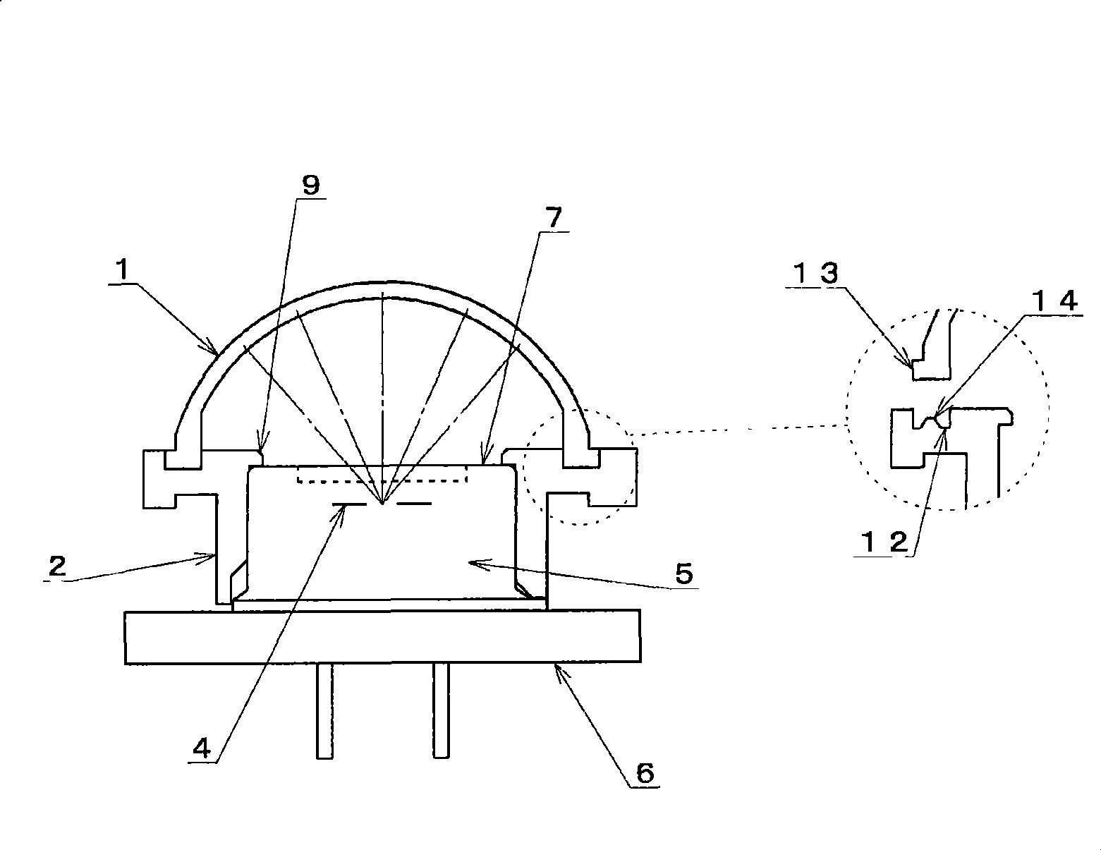
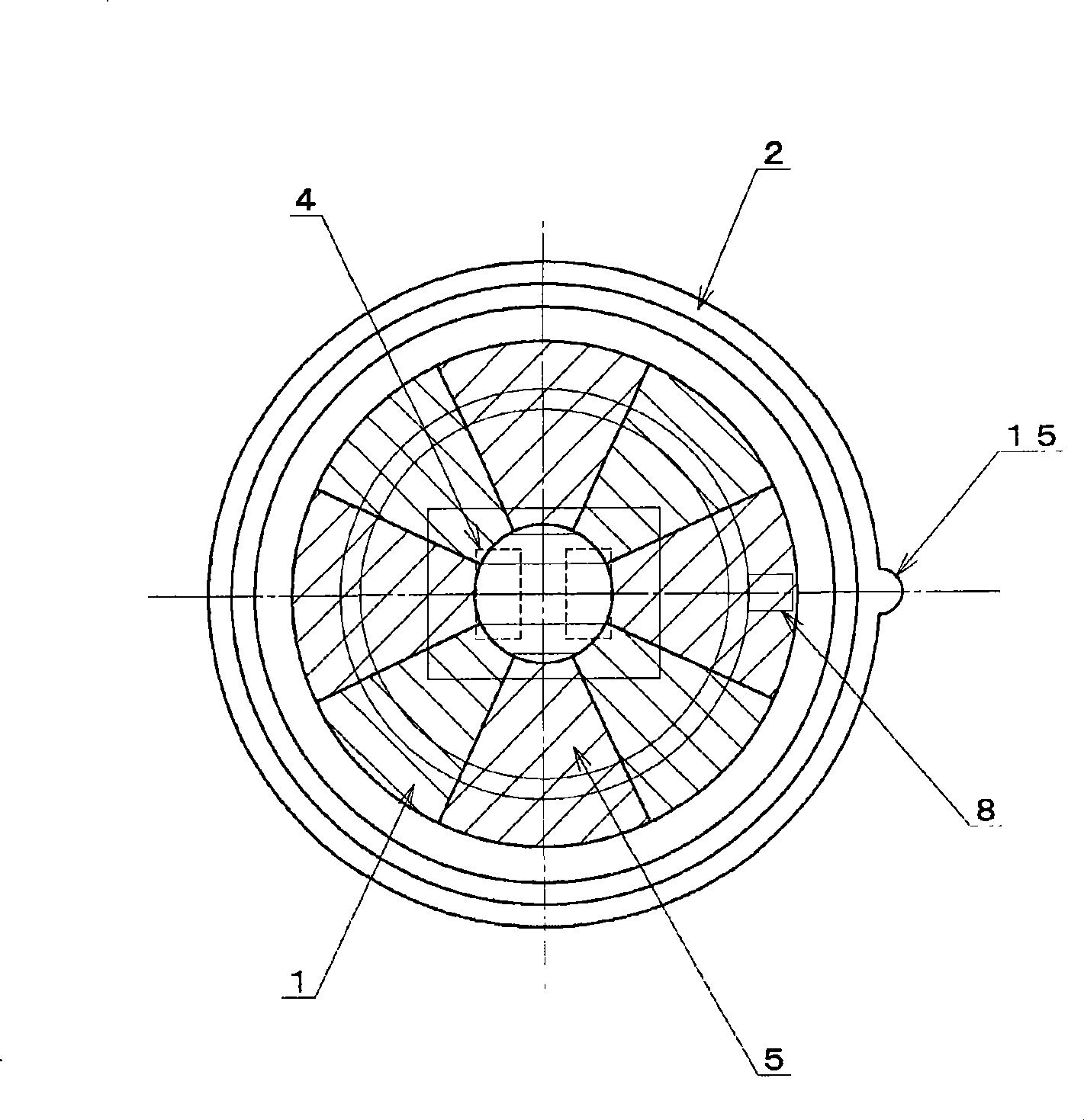
[0032] First refer to figure 1 and figure 2 , which relates to the resin molded optical lens of the present invention in detail. In the first embodiment, an optical lens that can be attached to a TO-5 pyroelectric infrared detector is taken as an example. The condensing lens 1 provided on the upper side is a thin-walled spherical lens that divides the infrared detection area into nine parts, and each lens part is made of a Fresnel shape. The focal distance relationship between each lens and the infrared light receiving element 4 is kept at 6.5mm±0.2mm, the spherical radius of the lens is designed to be 6.7mm±0.2mm. Installed to the lower side support part 2 on the TO-5 type pyroelectric infrared detector 5, the top of the detector case 7 and the detector TAB8 become installation suppression points, and the suppression part 9 on the inner surface side of the above-mentioned support part 2 and the bottom part Two support points 10 and 11 punched along the detector TAB8 are ...

Embodiment 2

[0038] use Figure 5 and Figure 6 , the mode of the invention related to the second embodiment will be described. Figure 5 Indicates that the optical lens used in Example 1 is oriented in the direction in which the second support point 11 of the lower support part 2 coincides with the detector TAB8, that is, the light distribution optical axis between the infrared light receiving element 4 and each lens part is relative to the regular reference axis The above perspective outline when rotated 45 degrees, Figure 6 express Figure 5 In the infrared detection device with Figure 4 The projected infrared detection area at a distance of 5m from the detection object set under the same conditions. At this time, as the optical axis of the lens unit changes, the size, shape, light distribution and Figure 4 Unlike the infrared detection area shown, the projected shape of the infrared detection area is a quadrilateral with a maximum width of 9.4m in the X direction and a maximum ...

Embodiment 3

[0040] Figure 7 Indicates a thin-walled spherical shape in which a Fresnel-shaped lens assembly with a focus distance of 5.8 mm ± 0.2 mm and an infrared detection area divided into 7 parts is formed and placed at a position with a spherical radius of 6 mm ± 0.2 mm. After the lens is assembled to the lower side support part used in Example 1 and Example 2, it is ultrasonically welded and installed in the infrared detection device installed on the dual type infrared detector 5 and Figure 4 and Figure 6 The infrared detection area where the detection object is 5m away from the detection object under the same setting conditions. The infrared detection region formed by the above-mentioned seven-divided optical lens is formed in a cross shape with a maximum width of 9.1 m in the X direction and a maximum width of 9.0 m in the Y direction.


PUM


Abstract

The present invention relates to a resin molded optical lens. The infrared ray for detecting object surface is assembled on a lens support section of the optical lens composed of resin and shaped size of the lens section, the shape and size of the lens section are limited in design because alive condition of such as injection molding. Resin molded product independently separated as infrared ray assembling lens section configured upper side and a support section mounted onto the an electrothermic detector is formed, the light assembling lens section and the support section are integrated into the optical lens after ultrasonic deposition. Further, according to the construction design of the infrared ray detection device, the upper side light assembling lens is changed, adjusted to be various lens having various infrared ray detection zones, thereby easily selecting separation or division of the infrared ray zones.

Description

technical field [0001] The present invention relates to a resin-molded optical lens for converging infrared rays from a human body to an infrared light receiving element included in a pyroelectric infrared detector mounted on a human body detection device. Background technique [0002] An infrared detection device using a pyroelectric infrared detector for the purpose of human body detection, etc., uses an optical lens that converges the emitted infrared rays from the detection target area to the infrared light receiving element arranged inside the pyroelectric infrared detector. The position is set in a manner consistent with that of the above-mentioned pyroelectric infrared detector, thereby constructing a design-divided infrared detection area. The above-mentioned optical lens generally uses a resin material made of an infrared-transmitting material. For example, when a certain range of detection object surface is divided into a plurality of infrared detection areas, it i...

Claims


Application Information

Patent Timeline
Patent Type & Authority Patents(China)
IPC IPC(8): G02B3/00
CPCG02B13/008G02B13/143G02B1/041
Inventor 平尾敏则木村亲吾近藤纯田中基树
Owner NIPPON CERAMIC CO LTD
Why Eureka
Try Eureka