Zoom lens system and a focusing method thereof

a zoom lens and lens group technology, applied in the field of zoom lens system, can solve the problems of inability to miniaturize the three-lens zoom lens system, the sensitivity of the focusing lens group becomes too high, and it is difficult to suitably correct aberrations from infinity to the closest photographing position

Inactive Publication Date: 2001-11-27
ASAHI KOGAKU KOGYO KK
View PDF9 Cites 7 Cited by
  • Summary
  • Abstract
  • Description
  • Claims
  • Application Information

AI Technical Summary

Benefits of technology

In the present invention, by integrally moving the first and second lens groups upon focusing, the number of lens elements constituting a lens group substantially performing an focusing operation is increased, whereby the correcting of aberrations from infinity to the closest photographing position becomes easier. This feature is unlike any well-known technology for focusing, i.e., only one lens group is arranged to perform focusing in a zoom lens system including a negative first lens group, a positive second lens group, and a negative third lens group, in this order from the object, while zooming is performed by moving the first through third lens groups along the optical axis.
Preferably, the first lens group includes two lens elements, and the second lens group includes three lens elements, and thereby, with a small number of the lens elements, aberrations can be suitably corrected from infinity to the closest photographing position.

Problems solved by technology

As a result, it becomes difficult to suitably correct aberrations from infinity to the closest photographing position with respect to any focal length points in an entire zooming range determined by the short focal length extremity and the long focal length extremity.
In order to correct aberrations suitably from infinity to the closest photographing position, the number of lens elements in the focusing lens group has to be increased, and therefore miniaturization of the three-lens-group zoom lens system cannot be achieved.
If KF exceeds the upper limit of condition (2), the sensitivity of the focusing lens group becomes too high, and it becomes difficult to perform a precise focusing operation.
If KF exceeds the lower limit of condition (2), the traveling distance of the focusing lens group becomes too long.

Method used


Image

  • Zoom lens system and a focusing method thereof
  • Zoom lens system and a focusing method thereof
  • Zoom lens system and a focusing method thereof

Examples


embodiment 2

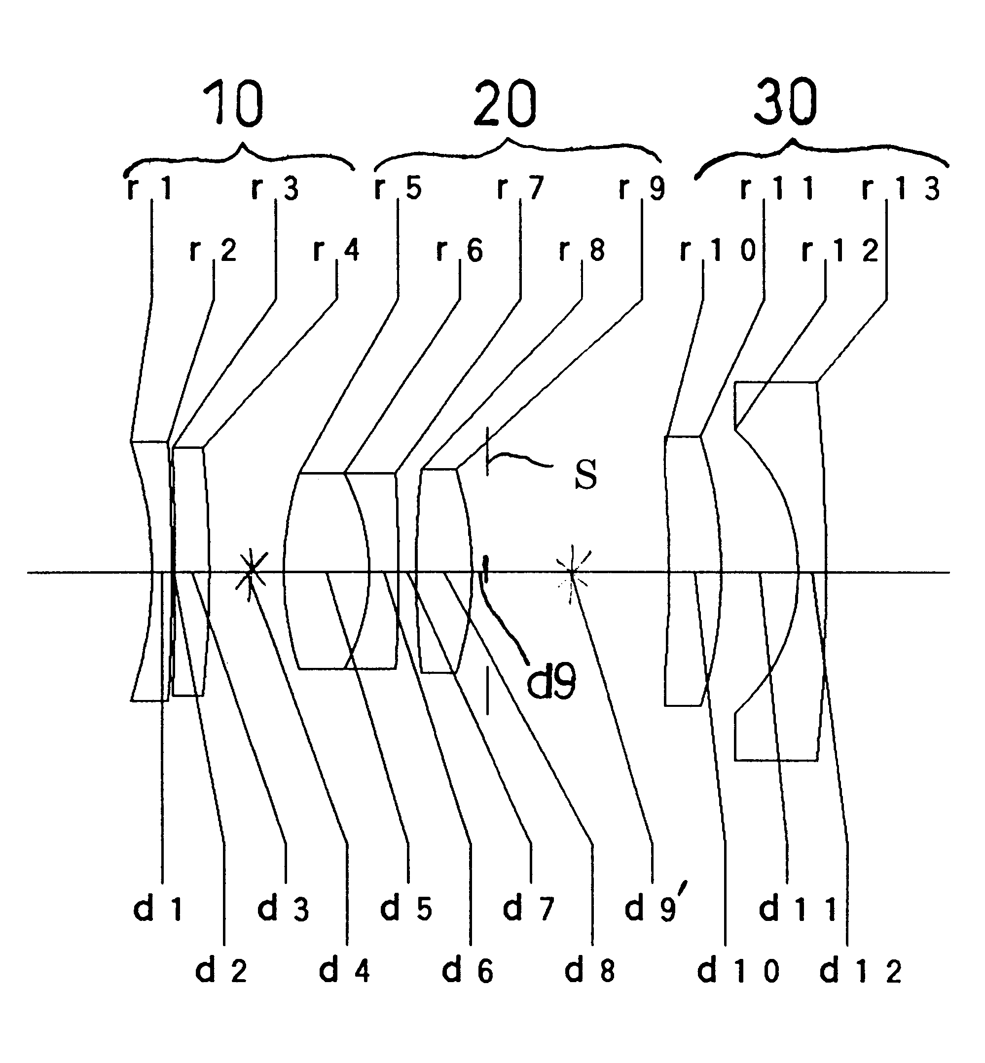
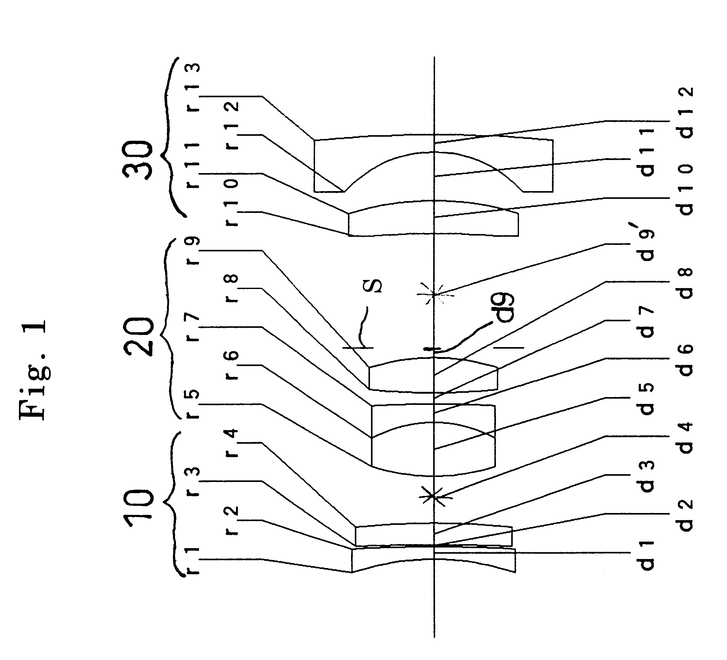
FIGS. 8 through 14 show the second embodiment of the zoom lens system. FIG. 8 is a lens arrangement of the second embodiment. FIGS. 9A through 9D, FIGS. 10A through 10D, and FIGS. 11A through 11D show aberration diagrams of the lens arrangement of FIG. 8, respectively at the short focal length extremity, at an intermediate focal length, and at the long focal length extremity, when the zoom lens system is focused at an infinite object distance. Further, FIGS. 12A through 12D, FIGS. 13A through 13D, and FIGS. 14A through 14D show aberration diagrams of the lens arrangement of FIG. 8, respectively at the short focal length extremity, at an intermediate focal length, and at the long focal length extremity, when the zoom lens system is focused at a finite object distance (an object-image distance: u=2.45 m). Table 2 shows the numerical data thereof. The basic lens arrangement is the same as the first embodiment.

embodiment 3

FIGS. 15 through 21 show the third embodiment of the zoom lens system. FIG. 15 is a lens arrangement of the third embodiment. FIGS. 16A through 16D, FIGS. 17A through 17D, and FIGS. 18A through 18D show aberration diagrams of the lens arrangement of FIG. 15, respectively at the short focal length extremity, at an intermediate focal length, and at the long focal length extremity, when the zoom lens system is focused at an infinite object distance. Further, FIGS. 19A through 19D, FIGS. 20A through 20D, and FIGS. 21A through 21D show aberration diagrams of the lens arrangement of FIG. 15, respectively at the short focal length extremity, at an intermediate focal length, and at the long focal length extremity, when the zoom lens system is focused at a finite object distance (an object-image distance: u=2.45 m). Table 3 shows the numerical data thereof. The basic lens arrangement is the same as the first embodiment.

Table 4 shows the numerical values of each condition in each embodiment.

A...


PUM


Abstract

A zoom lens system including a negative first lens group, a positive second lens group, and a negative third lens group, in this order from the object, and thereby upon zooming, the three lens groups independently move along the optical axis. On the other hand, upon focusing, the first and second lens groups, which move independently upon zooming, move integrally along the optical axis.

Description

1. Field of the InventionThe present invention relates to a zoom lens system for a compact camera, and in particular, relates to a focusing operation thereof.2. Description of the Related ArtIn a zoom lens system for a compact camera, there is no need to provide a long back focal distance, unlike a zoom lens system for a single lens reflex (SLR) camera which requires a space for providing a mirror behind the photographing lens system. Accordingly, a compact camera generally employs a telephoto type lens system in which positive and negative lens groups are provided in this order from the object, while a SLR camera generally employs a retrofocus type lens system in which negative and positive lens groups are provided in this order from the object.In a compact camera employing a telephoto type lens system, there has been a demand, in recent years, for a higher zoom ratio in a zoom lens system. In order to respond to this demand, a three-lens-group zoom lens system has been frequently ...

Claims


Application Information

Patent Timeline
Patent Type & Authority Patents(United States)
IPC IPC(8): G02B15/177G02B15/20G02B13/18
CPCG02B15/177G02B15/143503
Inventor ENOMOTO, TAKASHI
Owner ASAHI KOGAKU KOGYO KK
Why Eureka
Try Eureka