Automotive fuel tank fill assembly
- Summary
- Abstract
- Description
- Claims
- Application Information
AI Technical Summary
Benefits of technology
Problems solved by technology
Method used
Image
Examples
Embodiment Construction
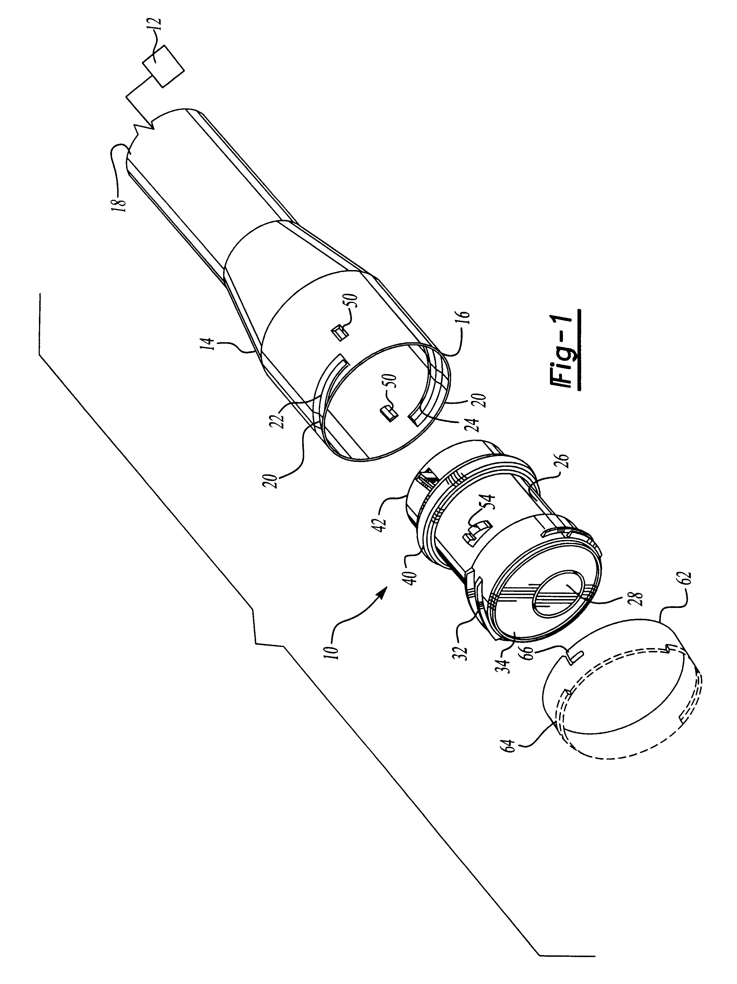
With reference first to FIG. 1, a preferred embodiment of the automotive fuel tank fill assembly 10 of the present invention is there shown for use with a fuel tank 12 (illustrated diagrammatically). The fuel tank fill assembly 10 includes a fill tube 14 having a first end 16 adapted to receive fuel and a second end 18 fluidly connected with the fuel tank 12.
The fill tube 14 is tubular and cylindrical in shape and includes at least one spiral indentation 20 adjacent its first end 16. This spiral indentation 20 forms both an external thread 22 as well as an internal thread 24.
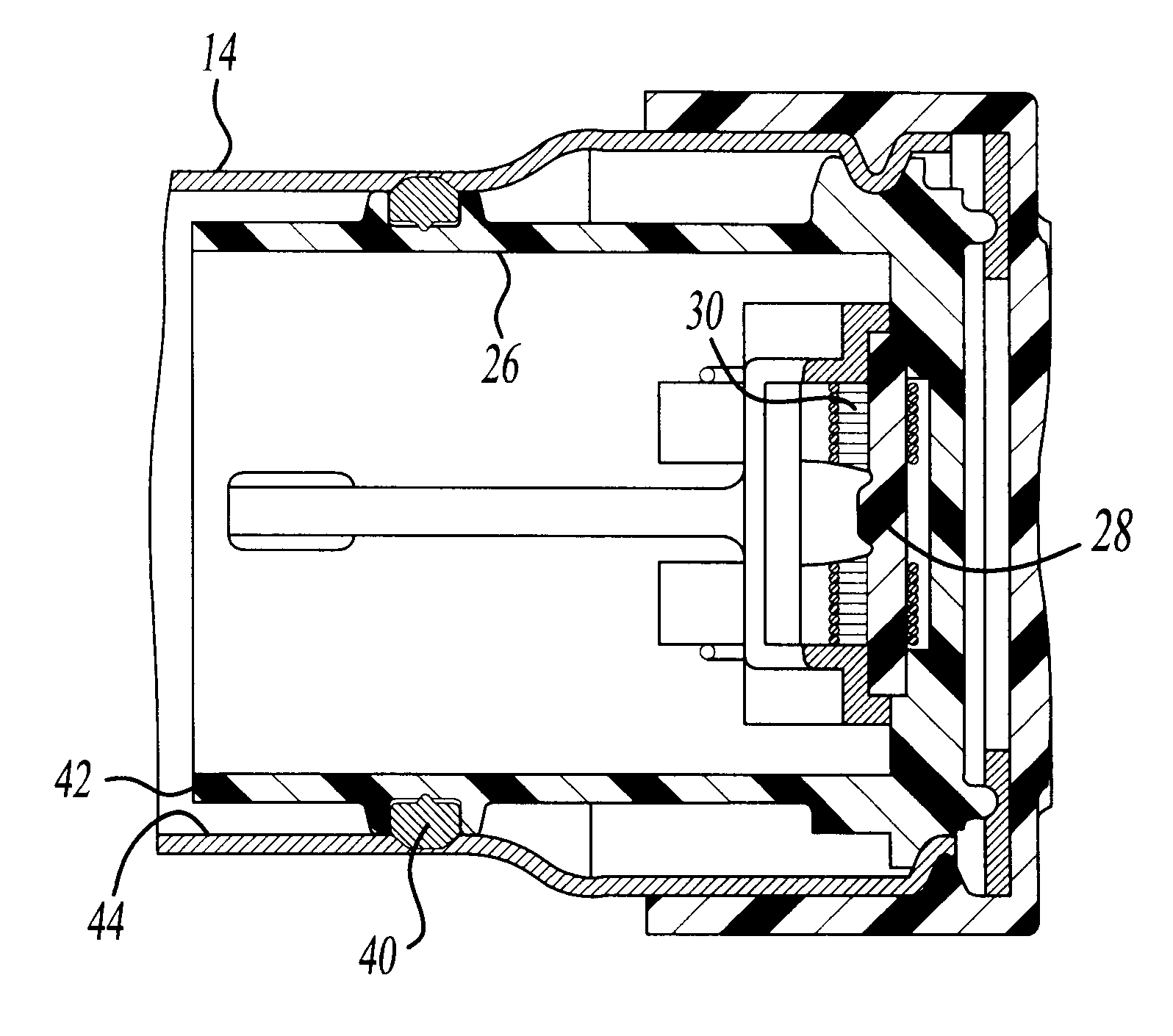
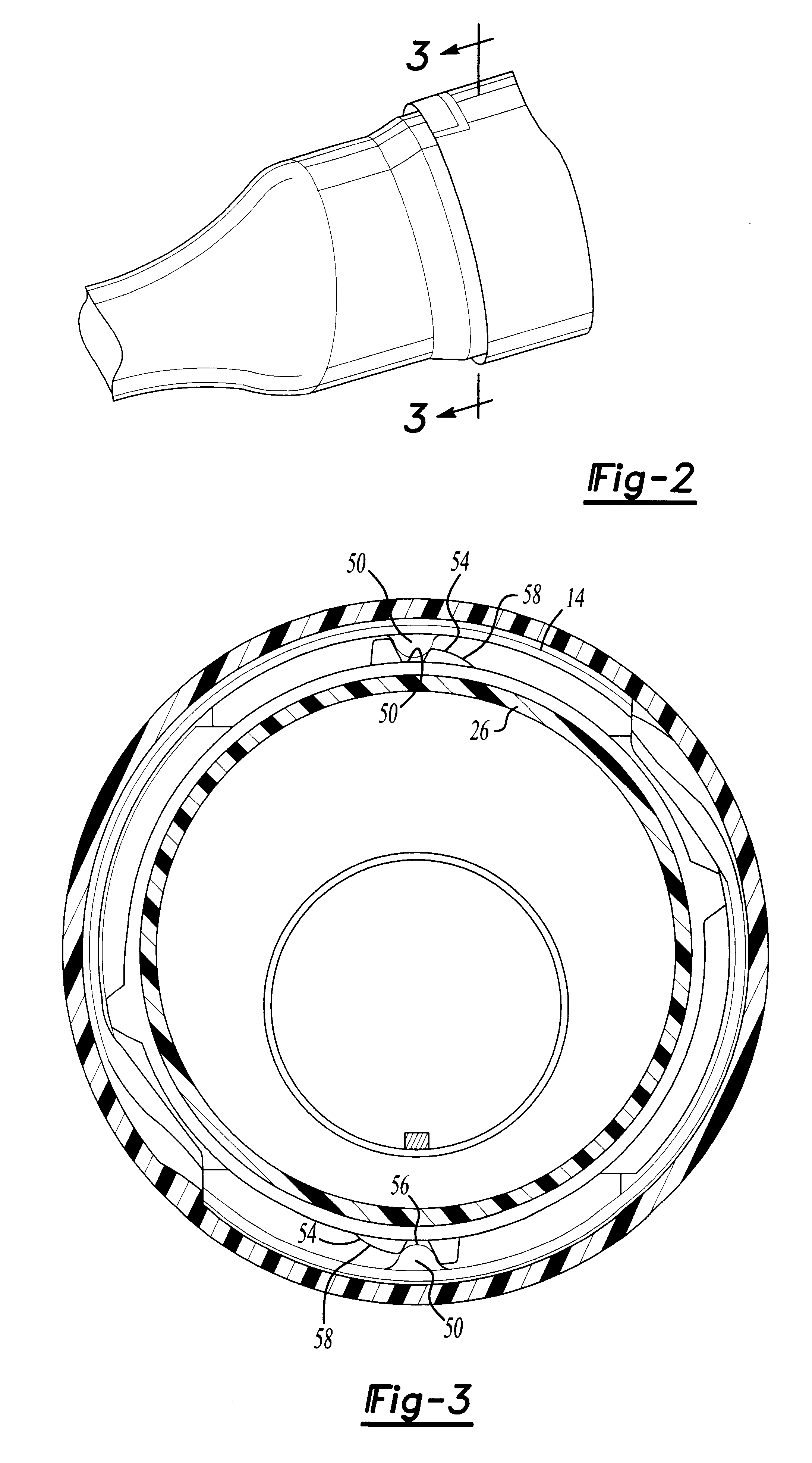
Referring now to FIGS. 1, 4 and 5, the fuel tank fill assembly 10 further includes an inlet valve housing 26 which is generally tubular and cylindrical in shape. Preferably, the inlet valve housing 26 is of a one piece construction and is preferably made from a plastic material.
The inlet valve housing 26 includes a normally closed inlet valve 28. This inlet valve 28 is retained in a normally closed position by a...
PUM
 Abstract
Description
Claims
Application Information
 - R&D
- Intellectual Property
- Life Sciences
- Materials
- Tech Scout
- Unparalleled Data Quality
- Higher Quality Content
- 60% Fewer Hallucinations
Browse by: Latest US Patents, China's latest patents, Technical Efficacy Thesaurus, Application Domain, Technology Topic, Popular Technical Reports.
© 2025 PatSnap. All rights reserved.Legal|Privacy policy|Modern Slavery Act Transparency Statement|Sitemap|About US| Contact US: help@patsnap.com


