
Firearms

a barrel and assembly technology, applied in the field of barrel assembly, can solve the problems of high pressure within the barrel, possible barrel damage, and series of undesirable peripheral recesses in the bor

Inactive Publication Date: 2002-02-05
DEFENDTEX
View PDF6 Cites 28 Cited by
  • Summary
  • Abstract
  • Description
  • Claims
  • Application Information

AI Technical Summary

Benefits of technology

Where the sealing band has a complementary part-conical inner face this ensures that the sealing band does not feather to a fine leading edge. It also provides sufficient radial space for positioning a sufficiently robust seal which will resist combustion pressures.

Problems solved by technology

Also the added locking effect, before such a failure, may result in very high pressures within the barrel and possible barrel damage.
While this was previously understood to be necessary it resulted in a series of undesirable peripheral recesses in the bore.

Method used


Image

  • Firearms
  • Firearms
  • Firearms

Examples


Embodiment Construction

In order that this invention may be more readily understood and put into practical effect, reference will now be made to the accompanying drawings which illustrate typical embodiments of the invention, wherein:

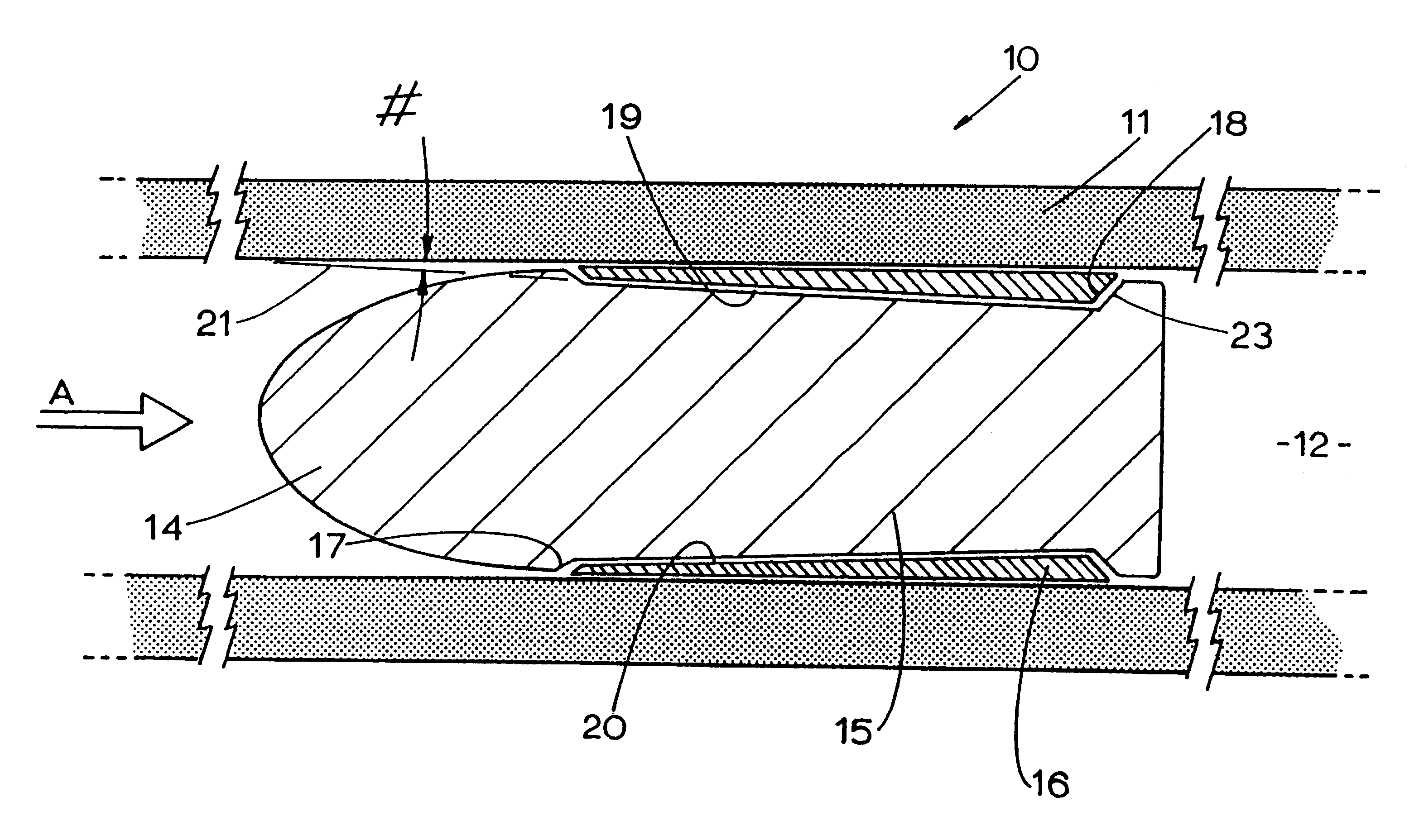
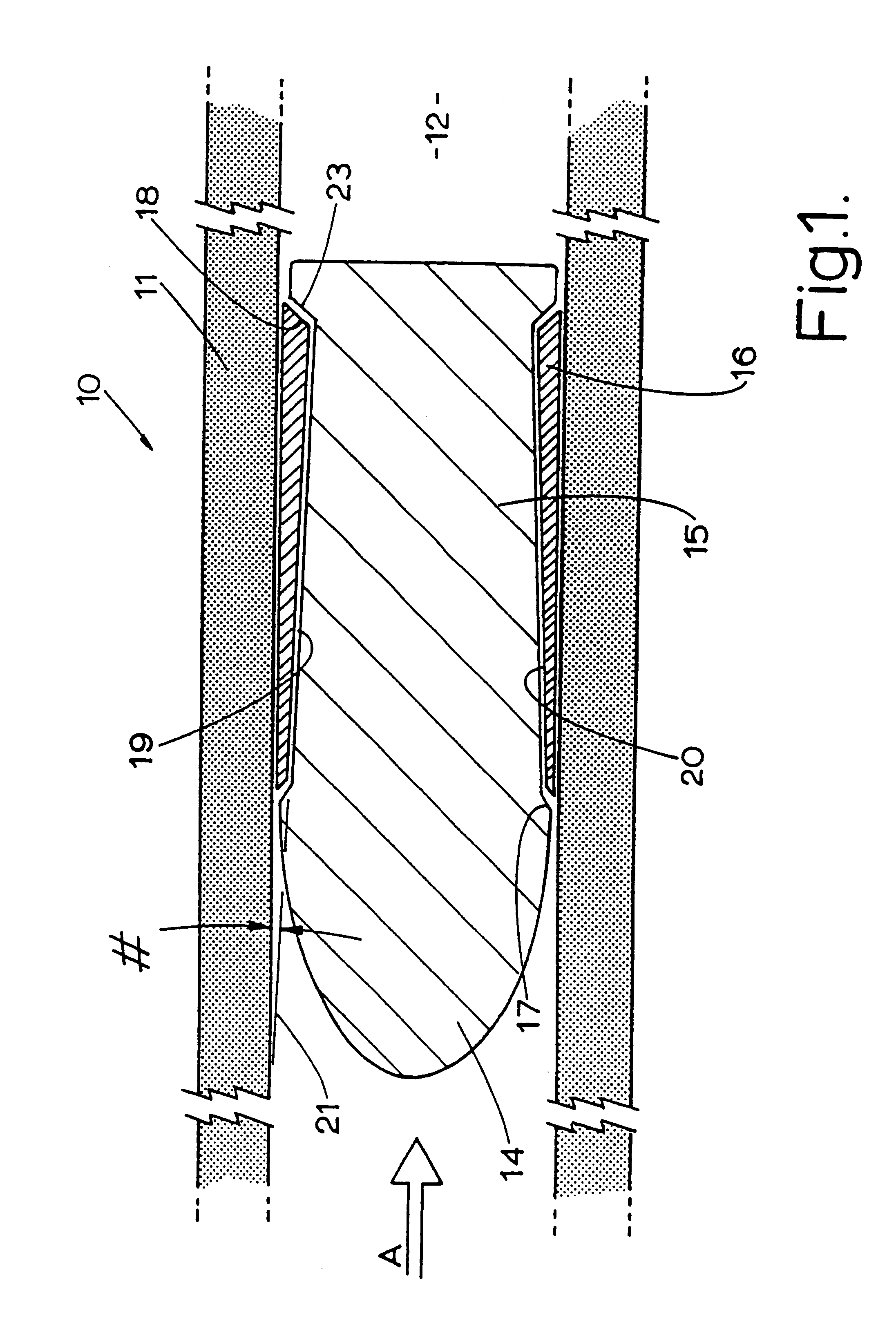
FIG. 1 is a diagrammatic cut-away view of a typical reverse wedging projectile according to one aspect of this invention;

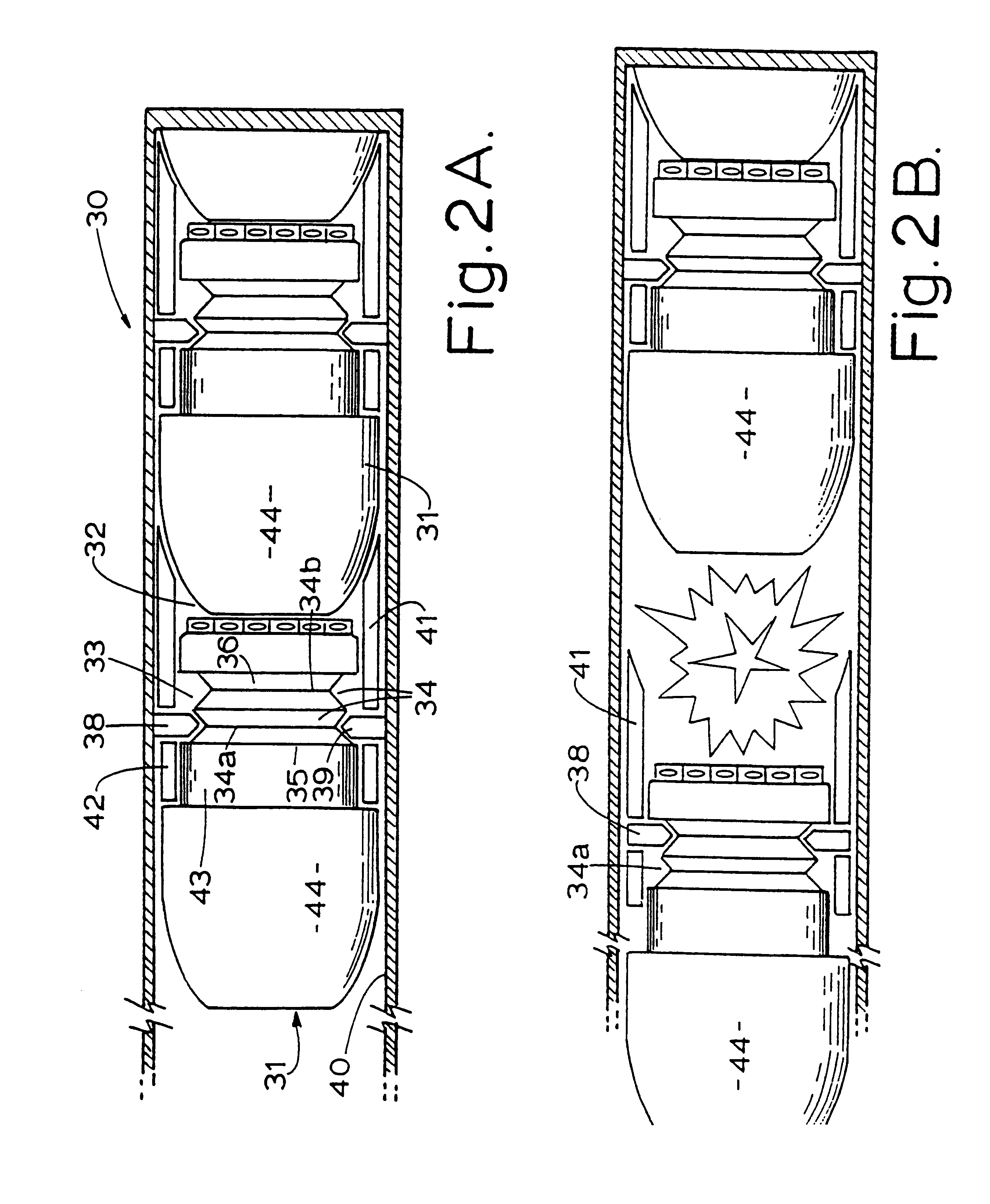
FIGS. 2A and 2B diagrammatically illustrate operation of a further reverse wedging projectile according to another aspect of this invention, and

FIG. 3 diagrammatically illustrates a further reverse wedging projectile according to yet another aspect of this invention.

According to the embodiment illustrated in FIG. 1, each projectile assembly 10 in a barrel of the type described is supported in a barrel 11 together with propellant in the trailing space 12 immediately behind the projectile assembly 10.

Each projectile assembly 10 includes a generally bullet shaped body part 14 having a part-conical rearwardly reducing trailing portion 15 which has an outer surfa...


PUM


Abstract

This invention provides a projectile assembly (10) having a body part (14) including a trailing portion (19) which reduces in diameter rearwardly and supports a sealing band (16) having a substantially cylindrical outer face for engagement with the bore (21) of the barrel (11). The body part (14) may move rearwardly through the sealing band (16) to expand it outwardly into sealing engagement with the bore (21). Upon firing the body part (14) moves forwardly relative to the sealing band (16) to free it from the bore (21).

Description

The invention relates to munitions and firearms.This invention has particular, but not exclusive, application to barrels each having a plurality of projectiles stacked axially within the barrel together with discrete selectively ignitable propellant charges for propelling the projectiles sequentially through the muzzle of the barrel and the sealing engagement between projectiles and barrel being such as to prevent rearward travel of the ignited propellant charge to trailing propellant charges. Such barrels will be referred to hereinafter as of the type described.This invention has particular application to munitions and firearms inventions described in my earlier International Patent Applications Nos. PCT / AU94 / 00124 and PCT / AU96 / 00459 and my co-pending patent applications.In my earlier International Patent Application No. PCT / AU96 / 00459 there is described a wedging action between the head part and the anvil part which effects a seal during firing. This seal ensures minimum loss of p...

Claims


Application Information

Patent Timeline
Patent Type & Authority Patents(United States)
IPC IPC(8): F41A21/00F41A21/06F41A21/28F42B5/00F42B5/03F42B14/02F42B14/00
CPCF41A21/06F41A21/28F42B14/02F42B14/00F42B5/035
Inventor O'DWYER, JAMES MICHAEL
Owner DEFENDTEX
Learn More