Structure of an antenna and method for manufacturing the same

a technology of antenna and structure, applied in the field of antennas, can solve the problems of frequency drift, inability to easily reduce, difficulty in keeping the rf characteristics stable,

Inactive Publication Date: 2002-02-05
ACCTON TECHNOLOGY CORPORATION
View PDF4 Cites 82 Cited by
  • Summary
  • Abstract
  • Description
  • Claims
  • Application Information

AI Technical Summary

Problems solved by technology

Typically, the antenna is one half or one quarter of a wavelength in length along at least one axis and as such cannot easily be reduced.
However, the conventional method for manufacturing an IFA antenna has difficulties in keeping the RF characteristics stable due to the antenna structure and the poor error tolerance in the manufacture process.
For instance, the soldering of the signal transmission line 16 may easily cause a frequency drift.
Moreover, the conventional method for manufacturing such an antenna is not efficient enough.

Method used


Image

  • Structure of an antenna and method for manufacturing the same
  • Structure of an antenna and method for manufacturing the same
  • Structure of an antenna and method for manufacturing the same

Examples


Embodiment Construction

The antenna of the invention is for transmitting / receiving radio frequency (RF) signals for a wide variety of wireless communications applications, including wireless local loop (WLL) services, cellular mobile radiotelephone services, and personal communications services.

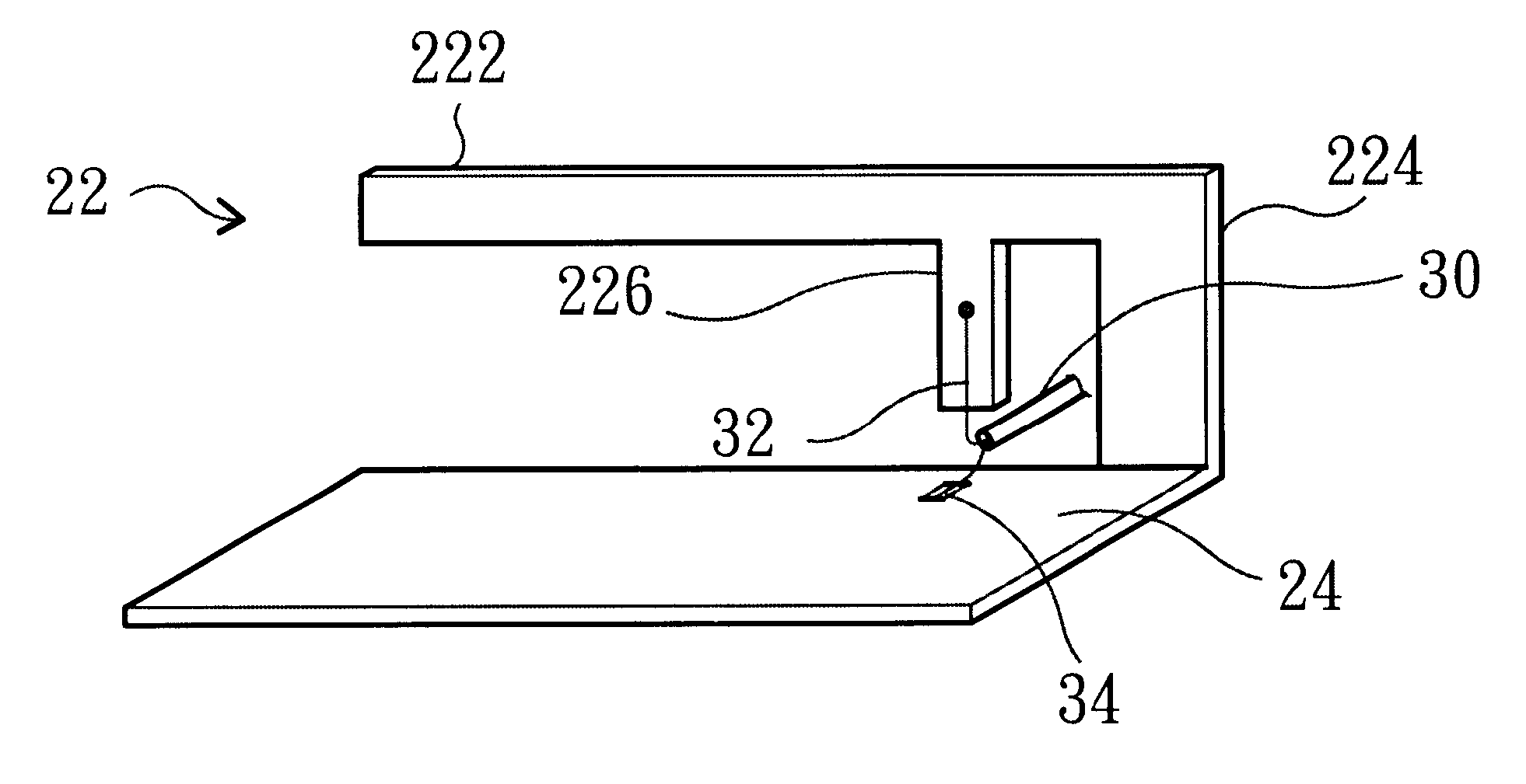
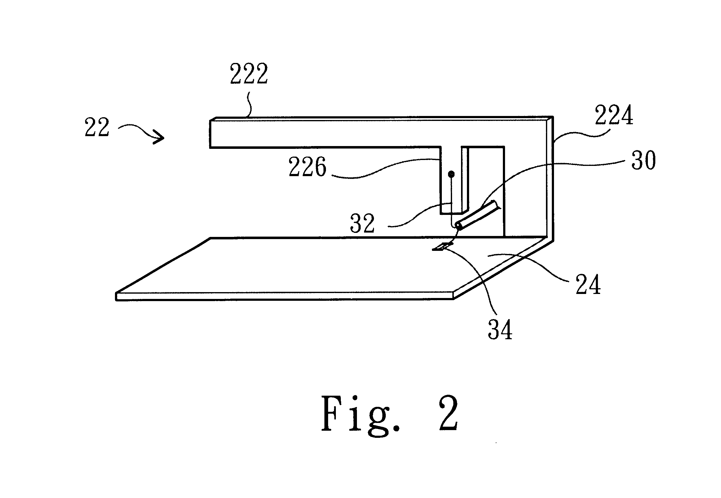
The improved Inverted-F structure of the antenna is illustrated in FIG. 2. Refer to FIG. 2, the antenna 22 includes a radiating portion 222, a support portion 224, a feed-in portion 226, a ground plane 24, and a signal transmission line 30. The Inverted-F structure is integrally formed with the ground plane 24 by molding or stamping. The signal transmission line 30 includes a core wire 32 and a ground wire 34. The signal transmission line 30 connects the feed-in portion 226 and a communication host (not shown) for transmitting the radio frequency signals to the communication host. The size of the ground plane 24 determines the quality of radio frequency transmission. A relatively large ground plane can provide bette...


PUM

PropertyMeasurementUnit
radio frequencyaaaaaaaaaa
frequencyaaaaaaaaaa
wavelengthaaaaaaaaaa

Abstract

A structure for an Inverted-F antenna includes: a radiating portion forming a longitudinal side of the Inverted-F antenna, a support portion integrally formed with the radiating portion and perpendicularly connected to the radiating portion, a feed-in portion integrally forming a center extending portion of the Inverted-F antenna and a signal transmission line connected to the feed-in portion and the ground plane for signal transmission between the antenna and a connected communication host. The signal transmission line includes a core wire and a ground wire. The core wire is connected to the feed-in portion and the ground wire is connected to the ground plane. The antenna is capable of keeping a stable radio frequency characteristic with its simple and compact structure.

Description

BACKGROUND OF INVENTION1. Field of the InventionThe present invention relates to an antenna and particularly to an omnidirectional wireless LAN antenna and a cost-effective method for producing the same.2. Description of the Prior ArtAn antenna is used for wireless radio frequency communications, including wireless local loop (WLL) services, cellular mobile radiotelephone (CMR) services, and personal communications services (PCS). An omnidirectional radio frequency antenna is commonly used at the central site for providing communication links between a central fixed site and multiple remote sites. Typically, the antenna is one half or one quarter of a wavelength in length along at least one axis and as such cannot easily be reduced.One type of a low-profile antenna is an Inverted-F Antenna (IFA) as shown in FIG. 1. A radiating portion 122 is connected to the end of the vertical element 124 of an inverted-L Antenna 12. A signal transmission line 16 is soldered to the radiating portio...

Claims


Application Information

Patent Timeline
Patent Type & Authority Patents(United States)
IPC IPC(8): H01Q9/04H01Q9/42
CPCH01Q9/0421H01Q9/42Y10T29/49016
Inventor DENG, TEN-LONG
Owner ACCTON TECHNOLOGY CORPORATION
Why Eureka
Try Eureka