Shell component for an aircraft fuselage and method of manufacturing the same

a technology for fuselage shells and aircraft, applied in the field of aircraft construction, can solve the problems of relatively high weight of structures, a relatively high cost and effort of materials and assembly work, and the present conventional fabrication of structural components such as fuselage shell components comprising plural skin-stringer-frame connections

Inactive Publication Date: 2002-04-02
DAIMLER CHRYSLER AEROSPACE AIRBUS
View PDF9 Cites 190 Cited by
  • Summary
  • Abstract
  • Description
  • Claims
  • Application Information

AI Technical Summary

Problems solved by technology

In view of such a multistep process, the present conventional fabrication of structural components such as fuselage shell components comprising plural skin-stringer-frame connect

Method used


Image

  • Shell component for an aircraft fuselage and method of manufacturing the same
  • Shell component for an aircraft fuselage and method of manufacturing the same
  • Shell component for an aircraft fuselage and method of manufacturing the same

Examples


first embodiment

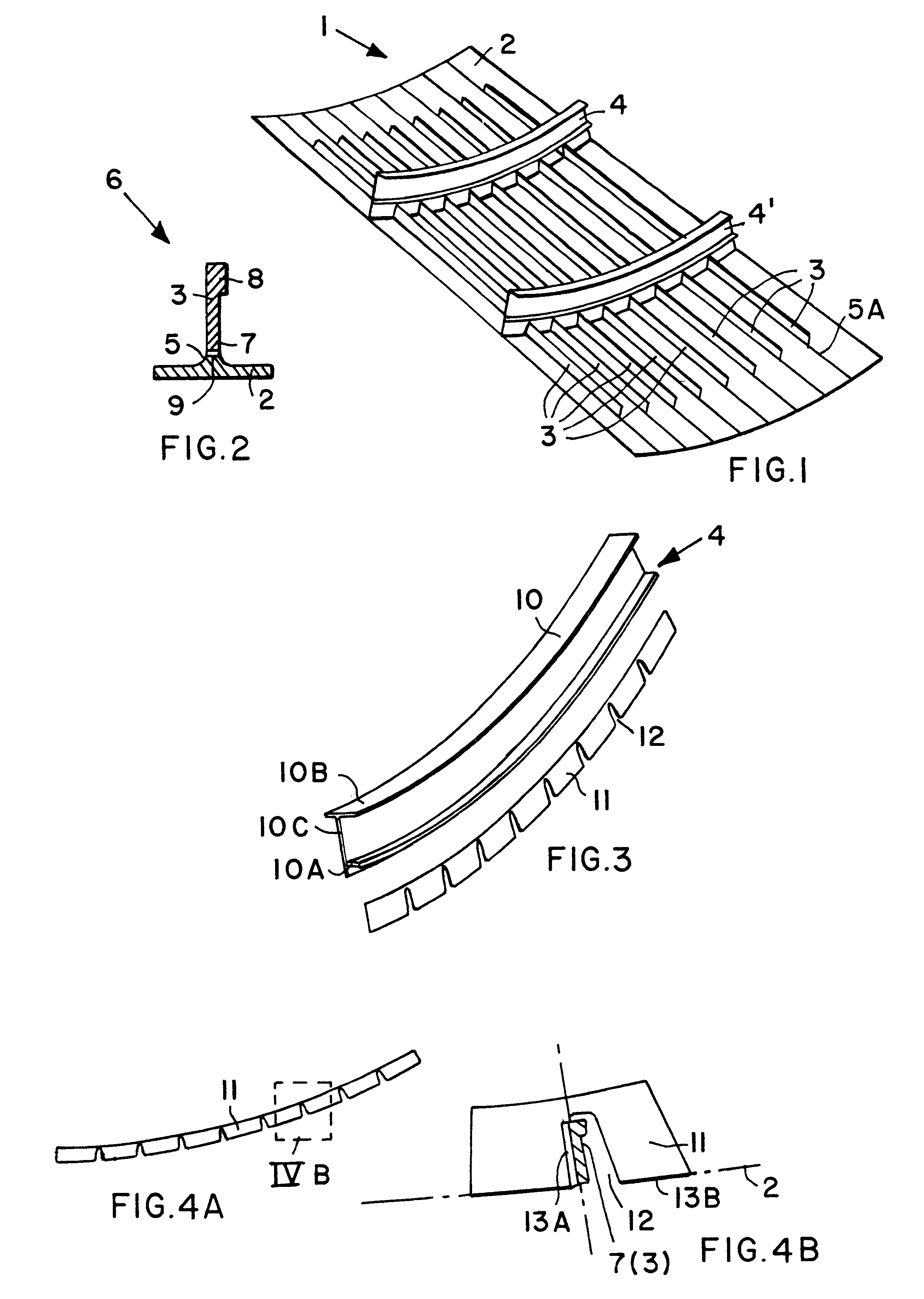
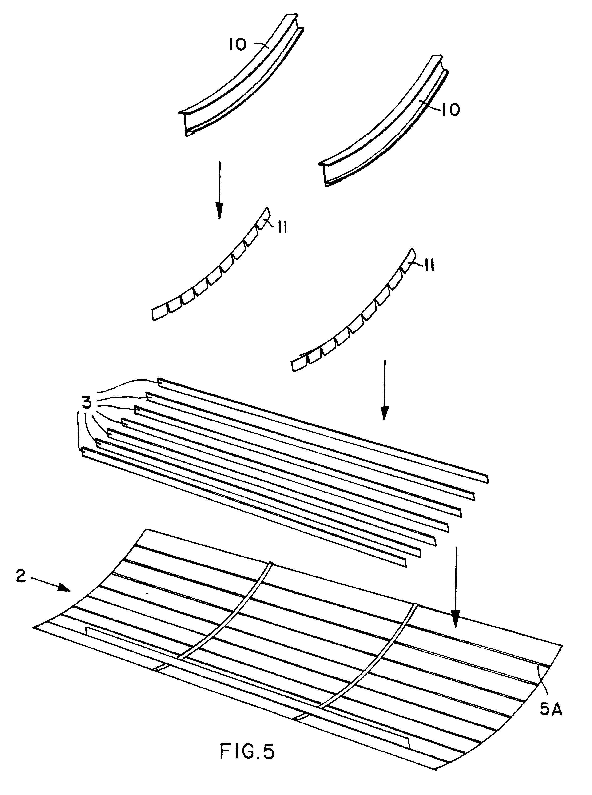
FIG. 1 shows a shell component 1 for an aircraft fuselage. A complete fuselage will essentially consist of a plurality of fuselage sections, which in turn each respectively consist of a plurality of prefabricated shell components 1 connected to each other. The prefabricated shell component 1 as shown in FIG. 1 essentially consists of a pre-curved or pre-formed skin sheet or panel 2 that is provided with stringers 3 extending in the lengthwise direction of the aircraft for strengthening the skin panel 2. Frames 4 and 4' are arranged extending crosswise relative to the stringers 3, i.e. substantially circumferentially relative to the lengthwise direction of the aircraft, whereby the respective frames 4 and 4' are spaced apart from each other in the aircraft lengthwise direction. The frames 4 and 4' serve to introduce and carry the loads from the control surfaces and empennage and the like into the aircraft fuselage.

In the illustrated first embodiment, both the stringers 3 and the fra...

second embodiment

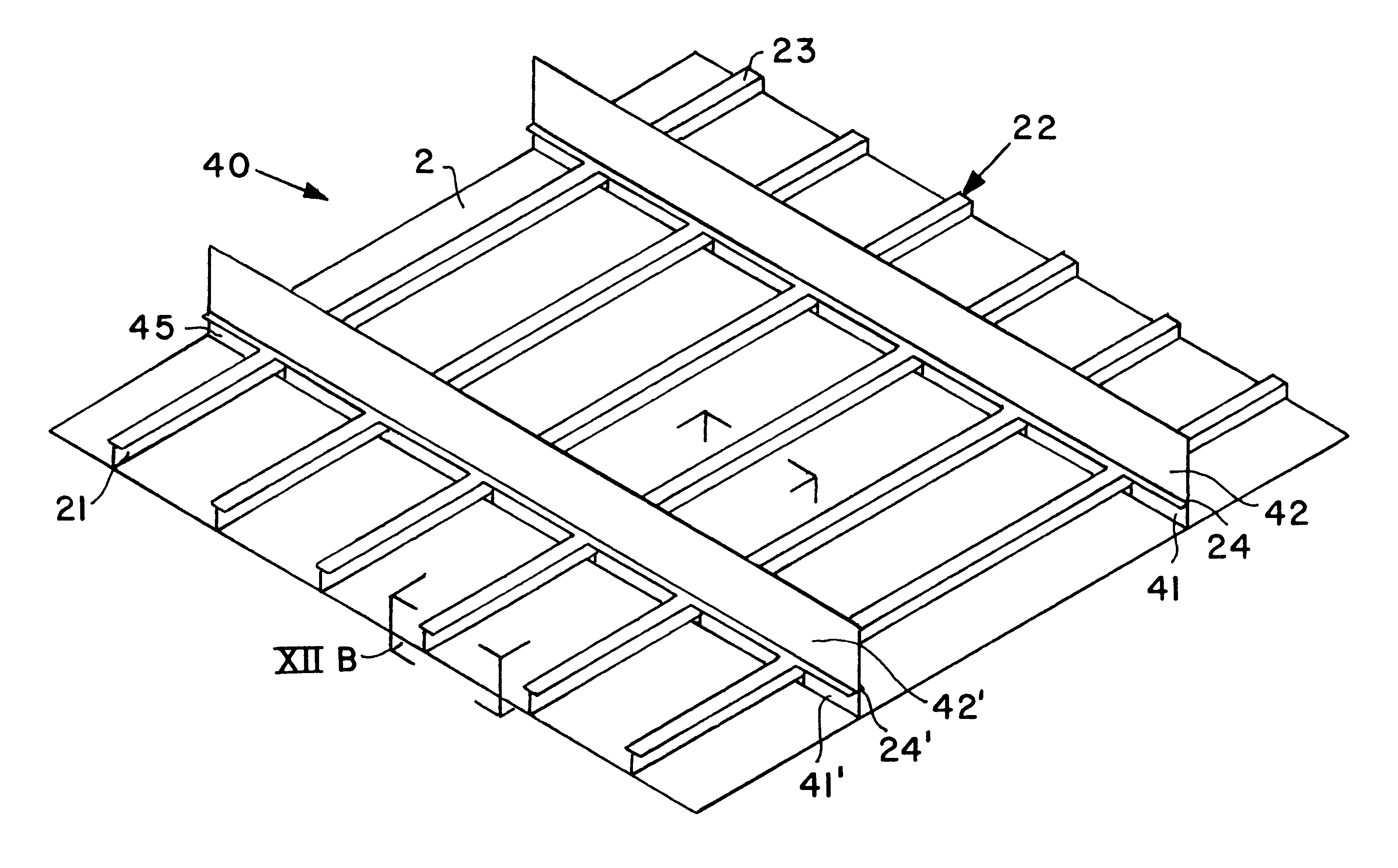
FIG. 6 shows a completely assembled shell component 20 for an aircraft fuselage, according to the invention. This shell component 20 essentially consists of a preformed skin panel 2, lengthwise extending stringer webs 21 welded onto the skin panel 2, and frame members as will be described below. The stringer webs 21 must have a curvature or contour in the lengthwise direction that matches the contour of the skin panel 2 in order to maintain a minimal spacing, or preferably a uniform contact between the respective contact surfaces of the skin panel 2 and the stringer webs 21. For this purpose, the stringer webs 21 can be cut particularly to have the proper contour, without requiring any subsequent machining or other shaping steps. Alternatively, the stringer webs may be formed from pre-cut blanks that initially have a straight cut contour, but are then deformed by stretch-forming in order to have the finished contour corresponding to the contour of the skin panel 2.

A stringer-frame g...


PUM

PropertyMeasurementUnit
Areaaaaaaaaaaa
Weldabilityaaaaaaaaaa

Abstract

A shell component for an aircraft fuselage includes a fuselage skin panel, a plurality of stringers extending in an aircraft lengthwise direction, and a plurality of frames extending crosswise relative to the stringers. The stringers and the frames are respectively welded onto the skin panel with the addition of a weld filler material. Each frame includes a frame root portion and a frame profile portion connected to each other. The frame root portion has cut-out notches receiving the stringers passing therethrough. The frame root portion is welded to the skin panel at the areas between the cut-out notches, and may be welded to the respective stringer in each cut-out notch. The stringers and frames are fabricated from webs and flanges, whereby a premanufactured grid of flanges may be used. The result is a very strong, yet simple shell component structure, that may be manufactured with a simple welding process, at a low cost and with low effort.

Description

PRIORITY CLAIMThis application is based on and claims the priority under 35 U.S.C. .sctn.119 of German Patent Application 198 44 035.9, filed on Sep. 25, 1998, the entire disclosure of which is incorporated herein by reference.The invention relates to a shell component for an aircraft fuselage comprising at least one metal skin sheet or panel, a plurality of stringers extending in the aircraft lengthwise direction, and a plurality of frame members extending crosswise relative to the stringers, i.e. in a direction generally circumferentially around the aircraft lengthwise direction. A welding supplemental or filler material is provided on the fuselage skin in the area of the connections between the stringers and the skin, and the stringers are welded onto the fuselage skin in these areas.BACKGROUND INFORMATIONIn the field of aircraft construction it is presently typical to use riveting or adhesive bonding for joining the fuselage skin panels onto the stringers to fabricate respective...

Claims


Application Information

Patent Timeline
IPC IPC(8): B64C1/00B64C1/12B23K9/00B23K26/00B23K26/20
CPCB64C1/12
Inventor BRINCK, PETERMUELLER, WILFRIEDSANMANN, KLAUS P.SPITZNER, JOERG
Owner DAIMLER CHRYSLER AEROSPACE AIRBUS
Why Eureka
Try Eureka