Liquid separator

Inactive Publication Date: 2002-04-09
GUILMETTE PAUL
View PDF18 Cites 63 Cited by
  • Summary
  • Abstract
  • Description
  • Claims
  • Application Information

AI Technical Summary

Problems solved by technology

A time delay is built into the electronics so that there is

Method used


Image

  • Liquid separator
  • Liquid separator
  • Liquid separator

Examples


second embodiment

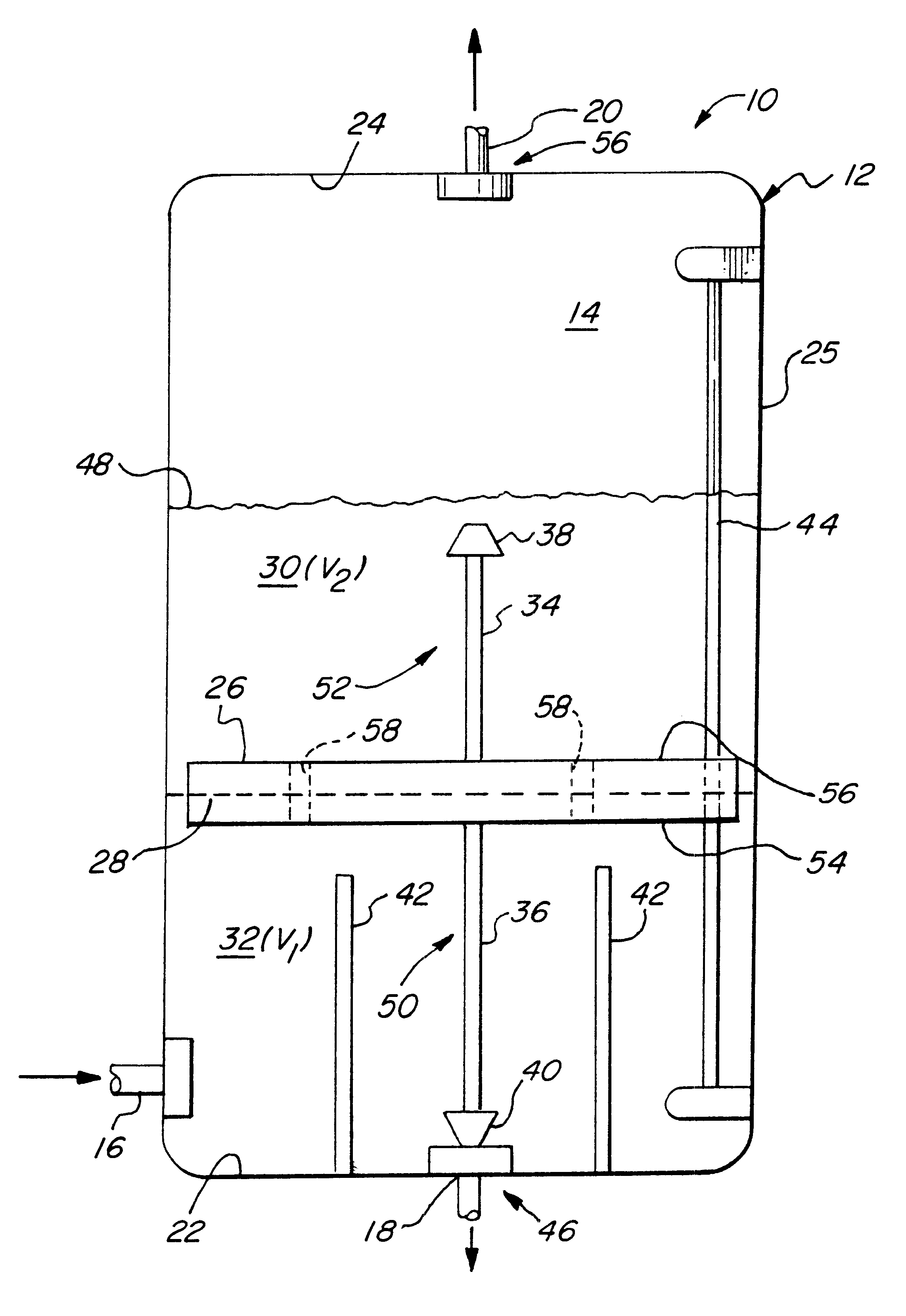
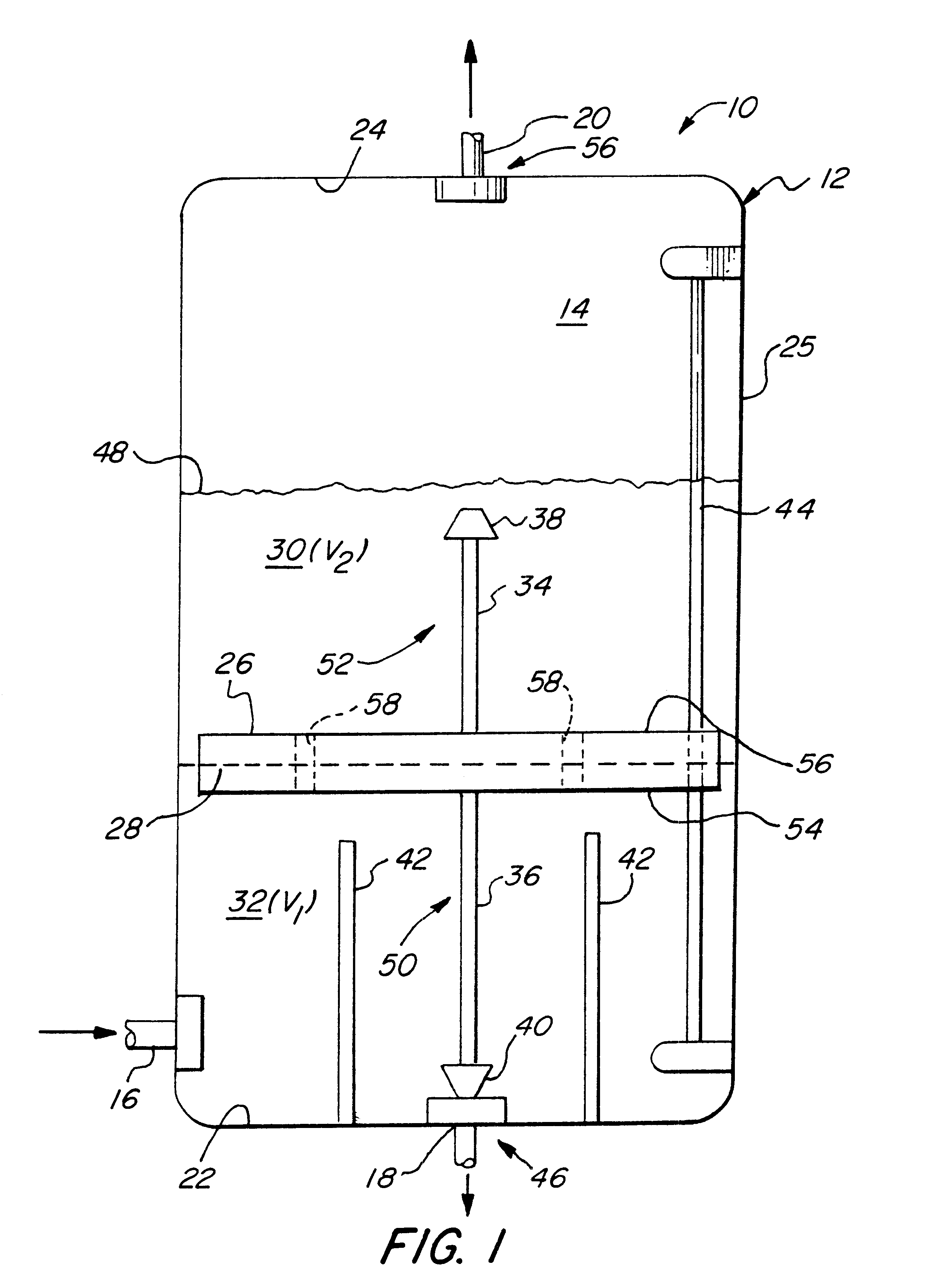
FIG. 2 illustrates a liquid separator 10 in which movement of the float 26 is guided in the vertical direction by a pair of support arms 60, 62 to which the first and second valve rods 36 and 64 are slidably connected. (The other components of FIG. 2 are numbered identically to those of FIG. 1 and function in substantially the same manner are not further described herein.) Second valve rod 64 is of greater length than first valve rod 36 that places the second valve closure member 38 in much closer proximity to the second valve 56 as compared to the embodiment of FIG. 1. If the proportion of oil to water in the mixture of first and second liquids is low, i.e., the ratio V.sub.1 / V.sub.2 is low, the relatively large volume of the water phase 32 raises the float 26 in the embodiment shown in FIG. 2, thereby opening first valve 46. This insures that the water is withdrawn via first liquid outlet 18 and that oil accumulates in the second volume V.sub.1 of oil phase 30 until the top liqui...

third embodiment

the invention is provided by the liquid separator 10" shown in FIG. 3. Liquid separator 10" is well suited for use in treating mixtures containing a relatively low proportion of first liquid (e.g., water) to second liquid (e.g., oil). Components of liquid separator 10" corresponding to those of FIG. 1 are identically numbered thereto and function is substantially the same way, and therefore are not further described herein. In FIG. 3, the valve rods 34, 36 of the embodiment of FIG. 1 are replaced by flexible connectors 74, 76, such as wires. One end of the second flexible connector 74 is connected to the top 56 of the float 26 and the other end is connected to a second valve 68. One end of the first flexible connector 76 is connected to the bottom 54 of the float 26 and the other end is connected to a first valve 70.

FIG. 4B illustrates a normally closed valve 68 which may be used in the second liquid outlet 20 of liquid separator 10" of FIG. 3. Valve 68 has a Y-shaped outlet channel...


PUM

PropertyMeasurementUnit
Lengthaaaaaaaaaa
Flow rateaaaaaaaaaa
Flexibilityaaaaaaaaaa

Abstract

A liquid separator (10) for separating two immiscible liquids having different specific gravities, for example, a first liquid comprising water and a second liquid comprising oil. The liquid separator (10) has a housing (12) that defines a separation chamber (14) and liquid inlet (16), a first liquid outlet (18) and a second liquid outlet (20) mounted above the first liquid outlet (18). A float 26 is positioned within separation chamber 14 to translate in the vertical direction and has a specific gravity between that of the first and second liquids so that it floats at approximately the interface (28) between the two liquid phases (30 and 32). Valve closure devices (38 and 40) contact valve seats in the valves 46 and 56 of first and second liquid outlets (18 and 20) to control the flow of separated liquids from separation chamber 14 as determined by the level of the interface (28) and the length of the valve rods (34 and 36).

Description

1. Field of the InventionThe present invention relates to devices for separating a combination of two immiscible liquids. More particularly, the present invention relates to mechanical devices for separating a combination of two immiscible liquids such as a mixture of oil and water as occurs in an oil spill in the ocean.2. Related ArtU.S. Pat. No. 4,436,630, issued to Anderson on Mar. 13, 1984 and entitled "Apparatus and Method for Separating a Mixture of Two Liquids", discloses an apparatus 10 for separating water from oil. As discussed therein, three floats 28, 30, and 32 are connected to switches 36, 38, and 40 which control the opening of valves 24 and 26 in outlets 16 and 18, respectively. The bottom two floats 28 and 30 will float on the more dense liquid, i.e., water, and the top float 32 will float on any liquid. As described, the water is removed from the outlet 16 and the oil is removed from the outlet 18. The opening and closing of the valves 24 and 26 is determined by th...

Claims


Application Information

Patent Timeline
IPC IPC(8): B01D17/02
CPCB01D17/0208B01D17/0211B01D17/0214Y10T137/3006
Inventor GUILMETTE, PAUL
Owner GUILMETTE PAUL
Why Eureka
Try Eureka