Arch cutting jig apparatus

a cutting jig and arch technology, applied in the direction of writing aids, circular curve drawing instruments, manufacturing tools, etc., can solve the problems of time-consuming and labor-intensiv

Inactive Publication Date: 2002-04-30
LOVETT PETER
View PDF1 Cites 8 Cited by
  • Summary
  • Abstract
  • Description
  • Claims
  • Application Information

AI Technical Summary

Problems solved by technology

This is tedious and time consuming, especially if there are multiple, varying--sized arches to make.

Method used


Image

  • Arch cutting jig apparatus
  • Arch cutting jig apparatus
  • Arch cutting jig apparatus

Examples


Embodiment Construction

The following description of the preferred embodiment of the invention is not to be taken in a limiting sense, but is made merely for the purpose of illustrating the general principles of the invention. The following detailed description is a suitably contemplated mode of carrying out the present invention. The spirit of the concept of this jig apparatus may be expressed in ways not mentioned here. One must interpret by an overall assesment.

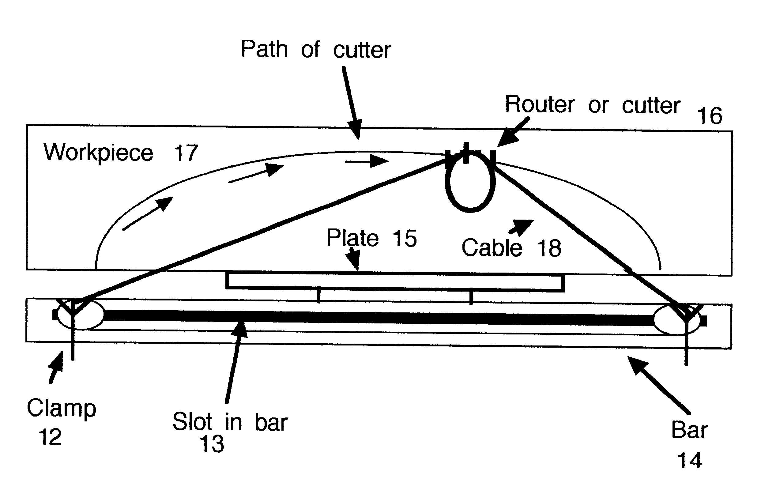
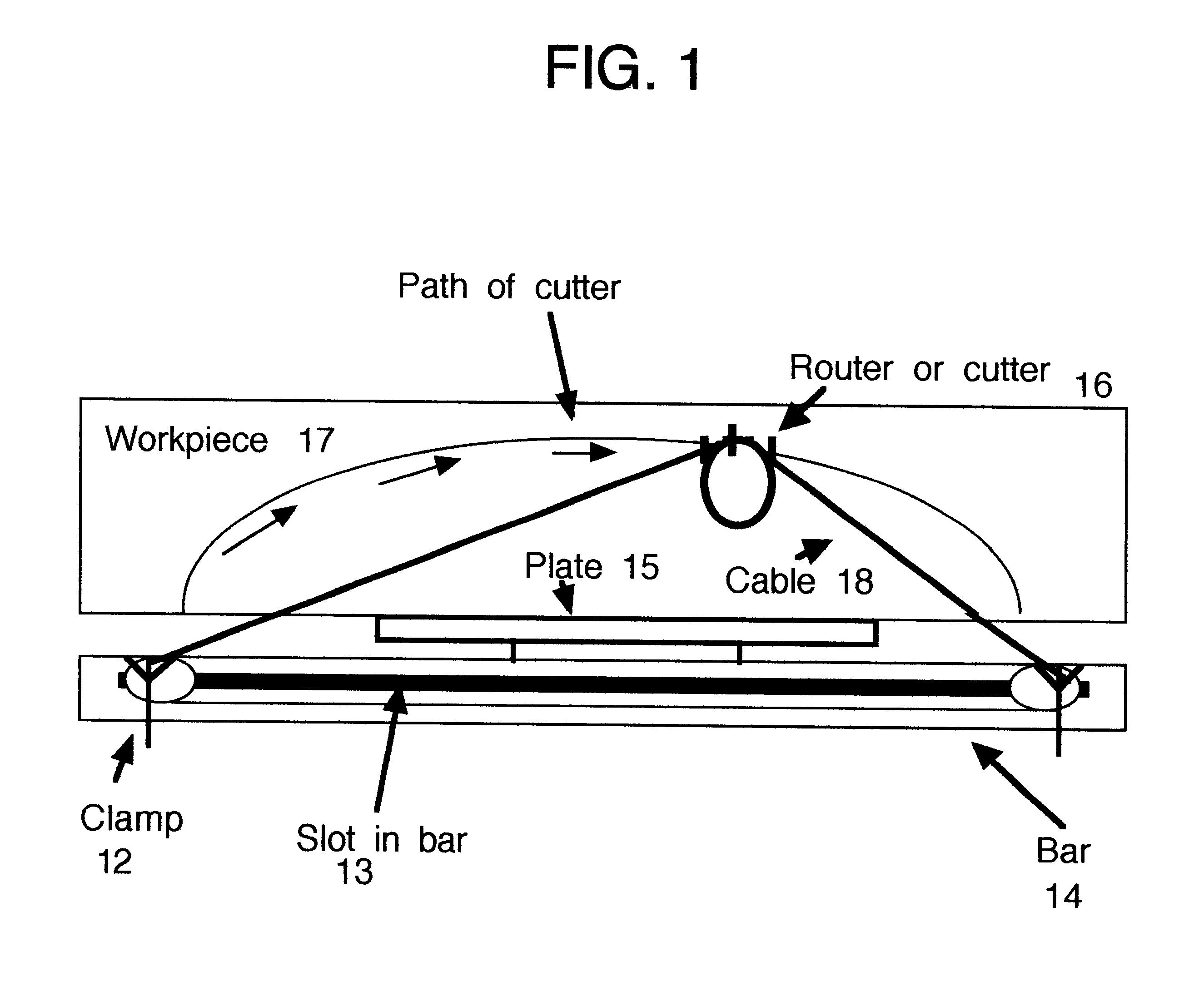
With reference now to the drawings and particularly to FIG. 1, the arch cutting jig apparatus is comprised of a bar 14 wooden or aluminum, having a slot 13 [See FIG. 3] which receives a sliding clamp 12. There are two sliding clamps 12 one on either side of the length-wise center point 19 [FIG. 2] of the bar. This present bar is 72" in length. The other dimensions of bar 14, thickness and depth, should be strong enough for the pressure exerted by the cutting tool 16 pulling against the bar 14. Wood should be at least 1" by 2", respectively, and m...


PUM


Abstract

A jig apparatus that allows one to cut arches in a work piece quickly and efficiently. It is comprised of a bar that has sliding adjustable clamps that secure a cable which go around pulleys on a router or other cutting device that when the cable is pulled taut, creates a path for the router or other cutting device to follow while it cuts thus cutting an arch into the work piece. Prior to this apparatus one would have to cut this arch with a template which had been previously tooled. This jig apparatus creates a template and cut all in one step.

Description

BACKGROUND OF INVENTIONAlthough there are many different jigs or devices made to make different size circles, there is no such item to make an arch. An arch differs from a circle in that it may vary in its proportions even as an elipse varies from a circle. This arch is not just an enlarged section of a circle, but may be a portion of an elipse. There are no other jigs available for purchase, that are made to cut arches with a router or other cutting tools.In the production of decorative arches that are used at the top of a bookcase, for instance, the width of the bookcase determines the width of the arch. If there are varying size widths, one would need varying sized arches. If the difference in widths is large, for example 12", a matching arch in a set of bookcases will be cut higher into one stock than on the other. If the center of the arch needs to maintain a reveal, such as 2", the two arches will need to vary in their spread. This jig is able to adjust to that change quickly ...

Claims


Application Information

Patent Timeline
Patent Type & Authority Patents(United States)
IPC IPC(8): B23Q3/00B23Q27/00B23Q1/54B23Q9/00B23Q1/25
CPCB23Q1/5468B23Q27/00B23Q9/00B23Q3/005
Inventor LOVETT, PETER
Owner LOVETT PETER
Why Eureka
Try Eureka