Roll screen

Inactive Publication Date: 2002-04-30
NICHIBEI CO LTD
View PDF19 Cites 39 Cited by
  • Summary
  • Abstract
  • Description
  • Claims
  • Application Information

AI Technical Summary

Benefits of technology

is to provide a roll screen in which a crashing sound and an impulse force cause

Problems solved by technology

In a final stage of the winding of the screen, since the winding diameter of the screen already wound becomes larger and a weight of a screen to be wound is reduced, a winding speed cannot be well controlled.
Therefore, there is a problem that when the screen is completely wound, a crashing sound caused by a weight bar attached at the bot

Method used


Image

  • Roll screen
  • Roll screen
  • Roll screen

Examples


Embodiment Construction

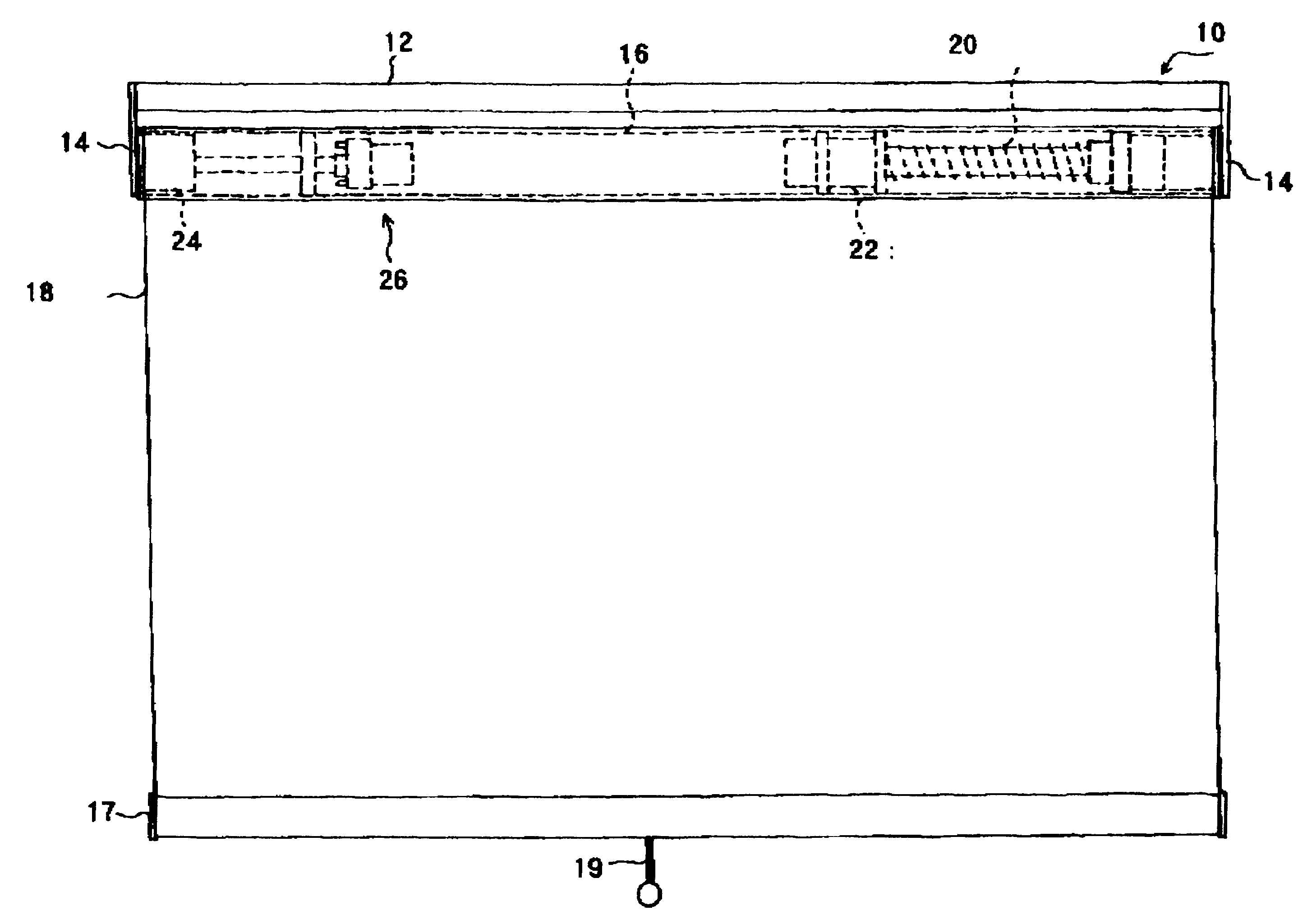
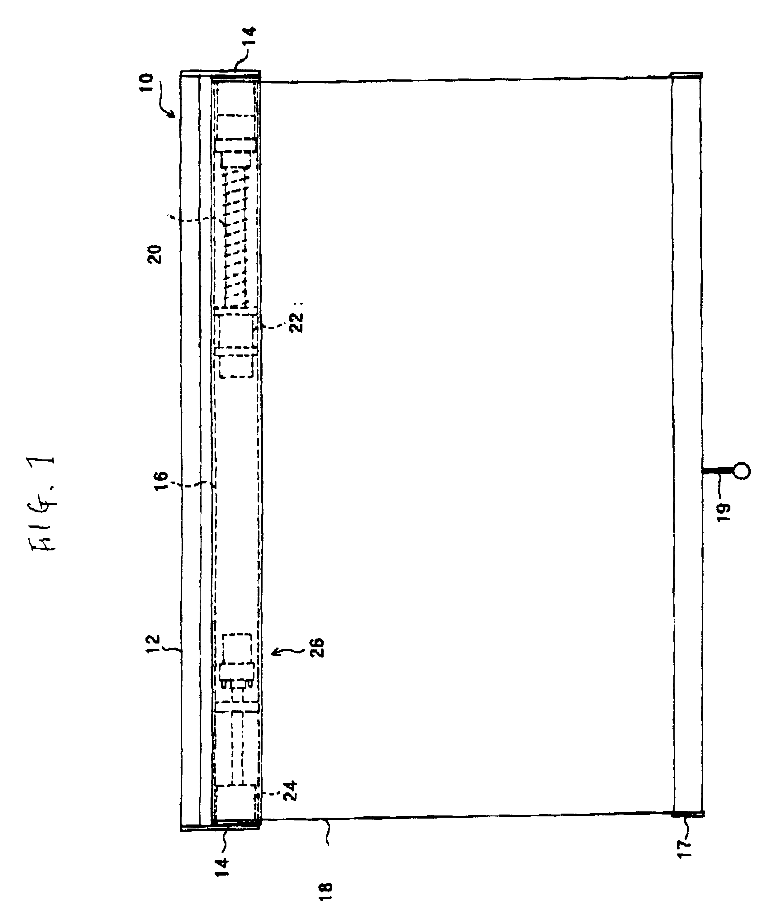
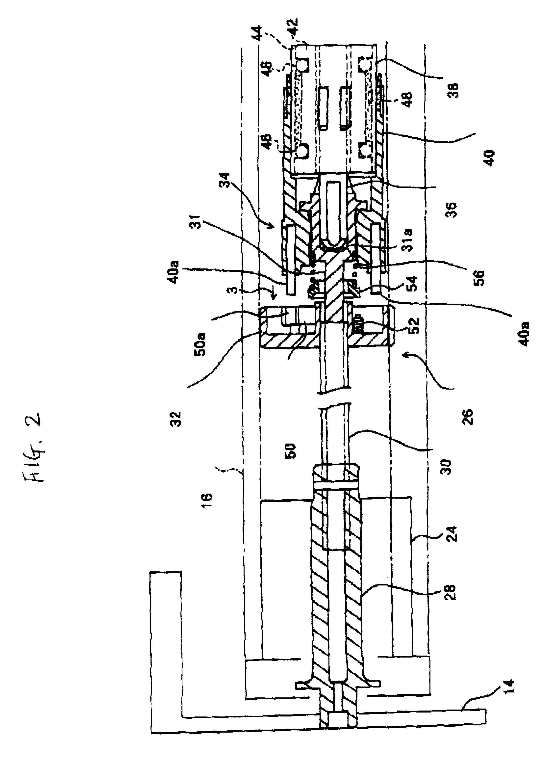
Referring now to FIGS. 1 to 5, there is shown a preferred embodiment according to the present invention.

FIG. 1 shows a roll screen according to an embodiment of the invention. Roll screen 10 mainly comprises a set frame 12 secured to a window frame and others, a pair of side plates 14 attached to the set frame 12, a winding pipe 16 rotatably supported to the side plates 14, a screen 18, a weight bar 17 attached to the lower end of the screen 18, and a pull device 19 attached to the lower end of the screen 18. One end of the screen 18 is connected with the winding pipe 16. The screen 18 is hung from the winding pipe 16 so as to be wound on or rewound from the winding pipe 16.

A coil spring 20 is mounted within the winding pipe 16. One end of the coil spring 20 is fixed to the side plate 14 indirectly, and the other end of the coil spring 20 is fixed to the winding pipe 16. If the winding pipe 16 is rotated in the rewinding direction of the screen, the other end of the coil spring 20 i...


PUM


Abstract

A roll screen comprises side plates, a winding pipe rotatably supported on the side plates, a spring mounted in the winding pipe, a screen to be wound on the winding pipe by the accumulated force of the spring, and a brake mounted in the winding pipe for decreasing a winding speed of the screen from a final stage of the winding of the screen. The clutch case is engaged with the brake from a final stage of the winding of the screen, and the brake is operated so that the winding speed of the screen can be decreased.

Description

1. Field of the InventionThe present invention relates to a roll screen, particularly to a roll screen in which a winding speed of the screen can be decreased.2. Description of the Related ArtA conventional roll screen has been disclosed in, for example, Published Unexamined Utility Model Application No. 26316 of 1983(Showa 58).This screen comprises a static screw which is securely arranged on a rotating axis for a winding pipe of a screen, a moving couple which is moved along the static shaft together with the rotation of the winding pipe, and a hydraulic damper mounted in the winding pipe. The hydraulic damper is provided with a piston rod and a piston which are moved in an axial direction together with the moving coupler, a cylinder secured to the winding sleeve, and oil filled in the cylinder. When the oil in the hydraulic damper is pressed by the piston rod moved together with the winding of the screen, a winding speed of the screen is decreased.In the screen provided the above...

Claims


Application Information

Patent Timeline
IPC IPC(8): E06B9/80G03B21/56G03B21/58E06B9/60E06B9/40E06B9/82
CPCE06B9/80G03B21/58E06B2009/808
Inventor YAMANAKA, HIROOMIEGAMI, KEN-ICHIROAKIMOTO, MASAYUKI
Owner NICHIBEI CO LTD
Why Eureka
Try Eureka