
Roll screen for reduction device

a technology of reducing device and roll screen, which is applied in the direction of door/window protective device, mechanical apparatus, vibration suppression adjustment, etc., can solve the problems of instantaneous winding, noise, and user surprise, and achieve the effect of preventing the winding of the roll screen

Inactive Publication Date: 2006-07-27
KWAK JAE SUK
View PDF6 Cites 21 Cited by
  • Summary
  • Abstract
  • Description
  • Claims
  • Application Information

AI Technical Summary

Benefits of technology

[0005] Accordingly, the present invention has been made to solve the above-mentioned problems occurring in the prior art. The object of the present invention is to provide a reduction device for a roll screen being capable of preventing a roll screen from winding instantaneously and giving a user a convenience.
[0006] Another object of the present invention is to provide reduction device for a roll screen being capable of preventing a noise, an impact and a safety-accident by remarkably reducing a winding speed of the roll screen as a compressive piston of a reduction part which is compressed into the cylinder with a rotating force of a rotating nut is nearly ceased by an air tight ring, and by softly winding the roll screen as an air in the piston is ejected slowly by an air-ejecting groove.
[0007] In order to accomplish these objects, according to the invention, there is provided an reduction device for a roll screen comprising a fixing axis formed in a winding bar and a damper combined with the fixing axis and reducing a winding speed of the roll screen, wherein the damper includes the fixing axis of which a screw thread part is formed on the peripheral surface, a inserting groove inserted a screen-inserting part of the winding bar, and one of a spring, a cushion, a bellows and a buffer between the reduction nut and the adjuster.

Problems solved by technology

Since the prior roll screen is wound instantaneously by an elastic force of a winding spring when the roll screen is wound around a winding bar, the instantaneous winding makes a user surprising and induces a noise.
That is, since the roll screen is wound around the winding bar by a elastic force of the winding spring put under torsional pressure, and the screen is wound faster and faster following the screen wounded with increasing speed, the handle bar bumps into a case collecting the winding bar, thereby a noise is occurred.

Method used


Image

  • Roll screen for reduction device
  • Roll screen for reduction device
  • Roll screen for reduction device

Examples


Embodiment Construction

[0019] Hereinafter, preferred embodiments of the present invention will be described with reference to the accompanying drawings. In the following description of the present invention, a detailed description of known functions and configurations incorporated herein will be omitted when it may make the subject matter of the present invention rather unclear.

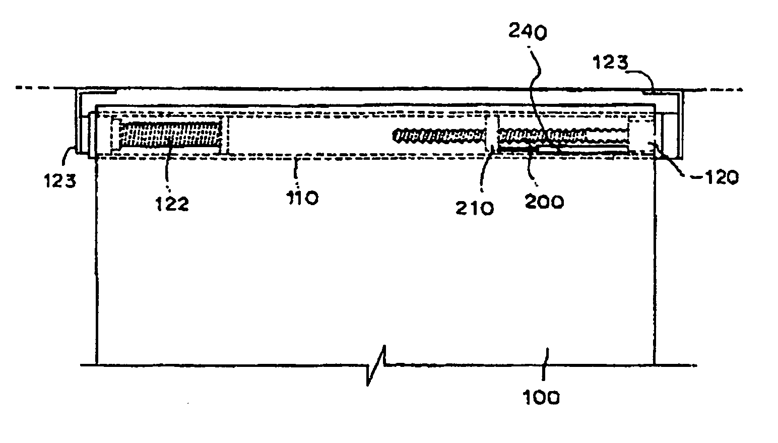
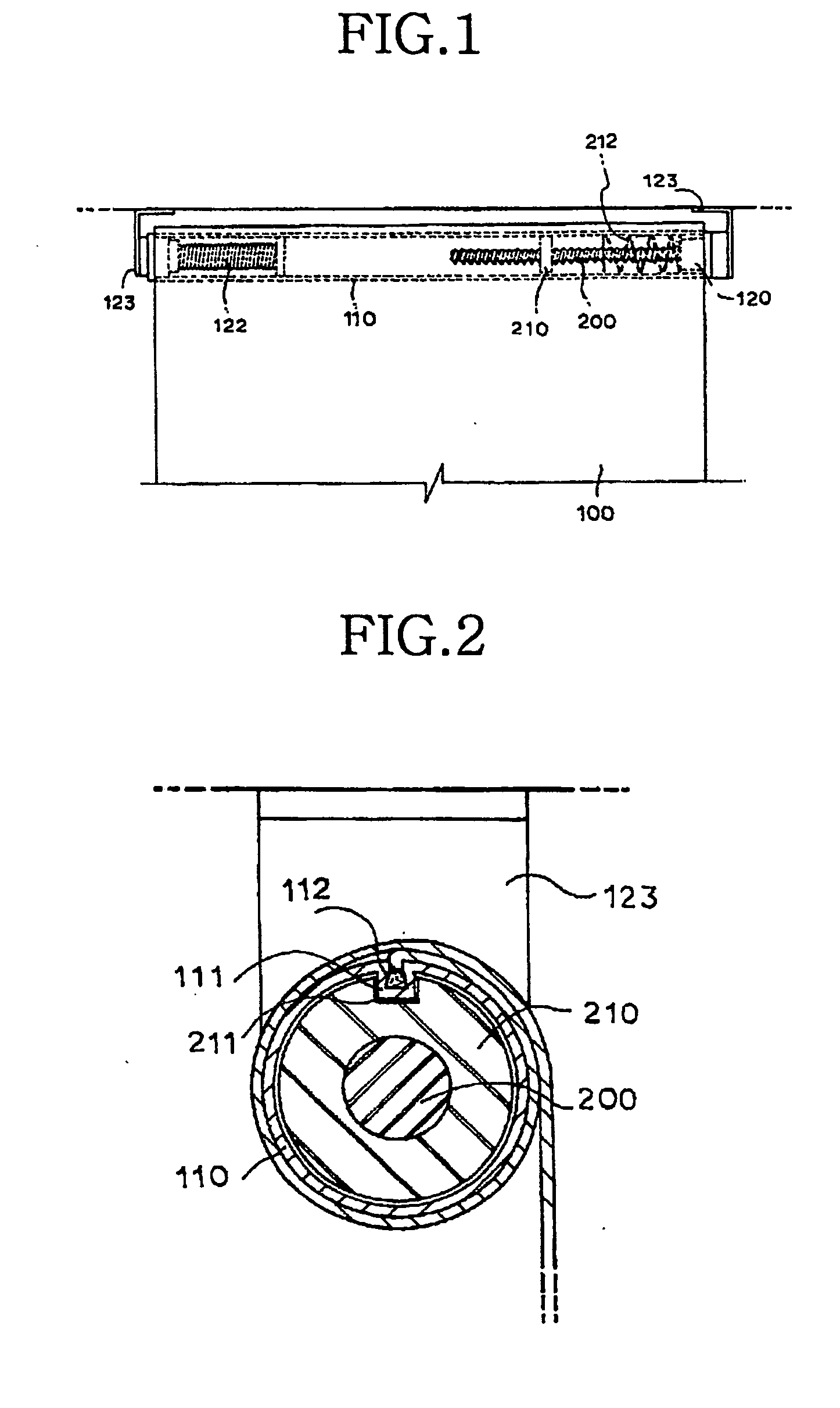
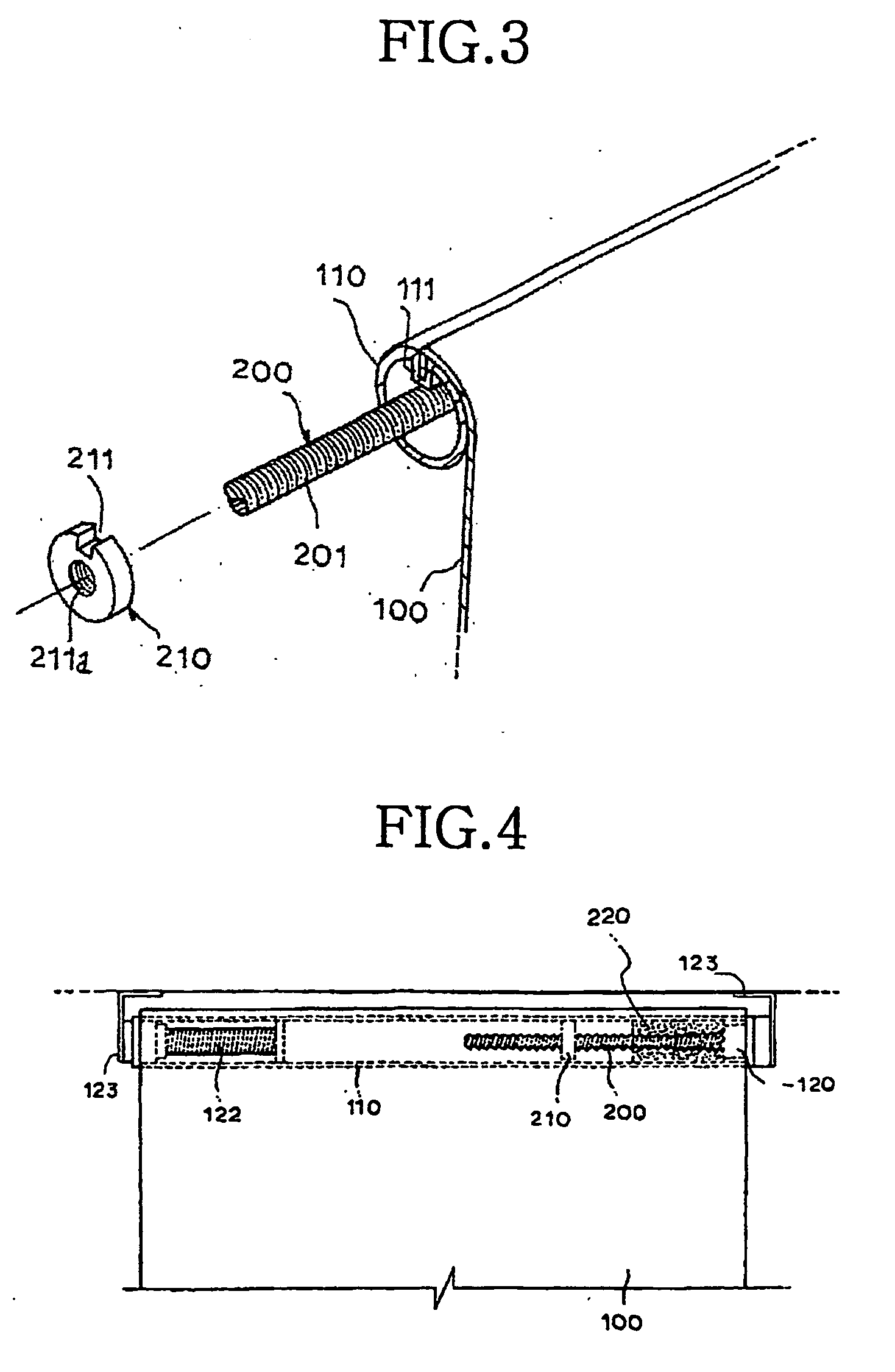
[0020]FIG. 1 and FIG. 2 show one embodiment of a reduction device for a roll screen according to the present invention comprising a roll screen 100, a winding bar 110 supporting the roll screen 100, wherein a bracket 123 is formed at both side ends of the winding bar 110 in order to install the roll screen 100 on a wall, a ceiling, a window frame, etc., and a winding spring 122 formed on one side of an inside of the winding bar 110.

[0021] The winding bar 110 further comprises a screen-inserting part 111 having a screen-inserting groove 112 in a longitudinal direction, and the roll screen is wound or unwound about the winding bar ...


PUM


Abstract

The present invention relates to a reduction device for a roll screen, as a compressive piston of a reduction part comes in and out inside of a cylinder combined with a one end of inside of a winding bar, to a device being capable of winding and loosening the roll screen easily and conveniently, more particularly to a device being capable of preventing a noise, an impact and a safety-accident and being capable of operating easily without distinction of age or sex, young and old, men and women all alike, due to a winding of the roll screen by way of reducing a speed of the roll screen with a definite section while the roll screen is wound.

Description

TECHNICAL FIELD [0001] The present invention relates to a reduction device for a roll screen, particularly to a device being capable of winding and unwinding the roll screen easily and conveniently, more particularly to a device being capable of preventing a noise, an impact and a safety-accident and being capable of operating easily without distinction of age or sex, young and old, men and women all alike, due to a winding of the roll screen by way of reducing a speed of the roll screen with a definite section while the roll screen is wound. BACKGROUND ART [0002] Generally, a roll screen is used in a substitution for a curtain, with operating in a way of winding or unwinding the screen round a winding bar, and when one pulls a handle bar, the screen is wound or unwinding by overcoming an elastic force of the winding spring. The roll screen may use as a decorative goods represented various photos, pictures and etc by taking a computer photograph, a substitute of a framed family-pict...

Claims


Application Information

Patent Timeline
Patent Type & Authority Applications(United States)
IPC IPC(8): E06B9/56E06B9/42E06B9/44E06B9/62E06B9/82
CPCE06B9/42E06B9/44E06B9/62E06B9/82E06B2009/808
Inventor KWAK, JAE-SUK
Owner KWAK JAE SUK
Learn More