Compressor muffler

a compressor and muffler technology, applied in the direction of liquid fuel engines, combustion air/fuel air treatment, positive displacement liquid engines, etc., can solve the problems of noise generation, noise generation, noise generation, etc., and achieve the effect of reducing noise, reducing noise, and reducing nois

Inactive Publication Date: 2002-05-07
RIC INVESTMENTS LLC
View PDF3 Cites 45 Cited by
  • Summary
  • Abstract
  • Description
  • Claims
  • Application Information

AI Technical Summary

Problems solved by technology

Compressing the gas generates noise from a variety of sources.
For instance, running the connecting rod assembly and sucking gas into the compressor during the downstroke of the piston generates noise through the compressor intake port.
Furthermore, compressing gas during the upstroke of the piston generates a noise that travels back through the compressor intake port, while the turbulent flow of the gas as it travels at high velocity into an output cylinder also generates acoustic noise in a pulse setting fashion.
Furthermore, these assemblies require numerous parts and typically occupy a large amount of space, which adversely impact the desirability of the muffler.
Another possible disadvantage with such a design is that a trade-off exists between adequately muffling the noise and producing a pressure drop across the muffler.
Such a pressure drop decreases the efficiency of the compressor.
While these types of resonators are effective, they generally require extensive design work on the particular compressor size and then only work on soundwaves of a particular frequency.
While many of these mufflers are believed to reduce the compressor noise, they are generally either difficult to design, only effectively reduce the sound associated with a particular wave frequency, or require many components which result in an increase cost of the muffler in both materials and assembly labor.
These portals separate the first flow of gas into a plurality of flows as the gas passes from a first side of the baffle to a second side of the baffle, thereby disturbing the first flow of gas and attenuating noise.

Method used


Image

  • Compressor muffler
  • Compressor muffler
  • Compressor muffler

Examples


Embodiment Construction

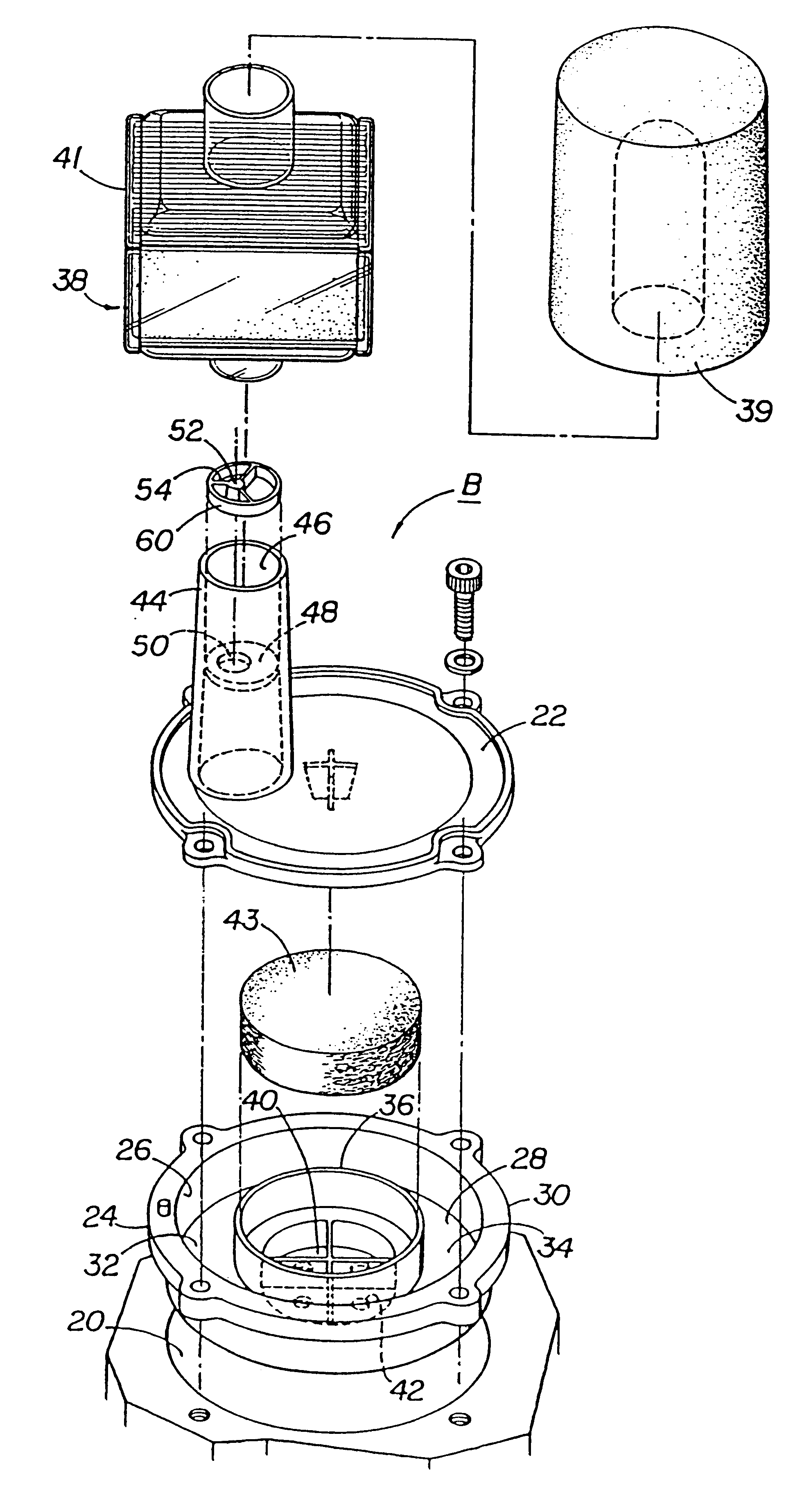
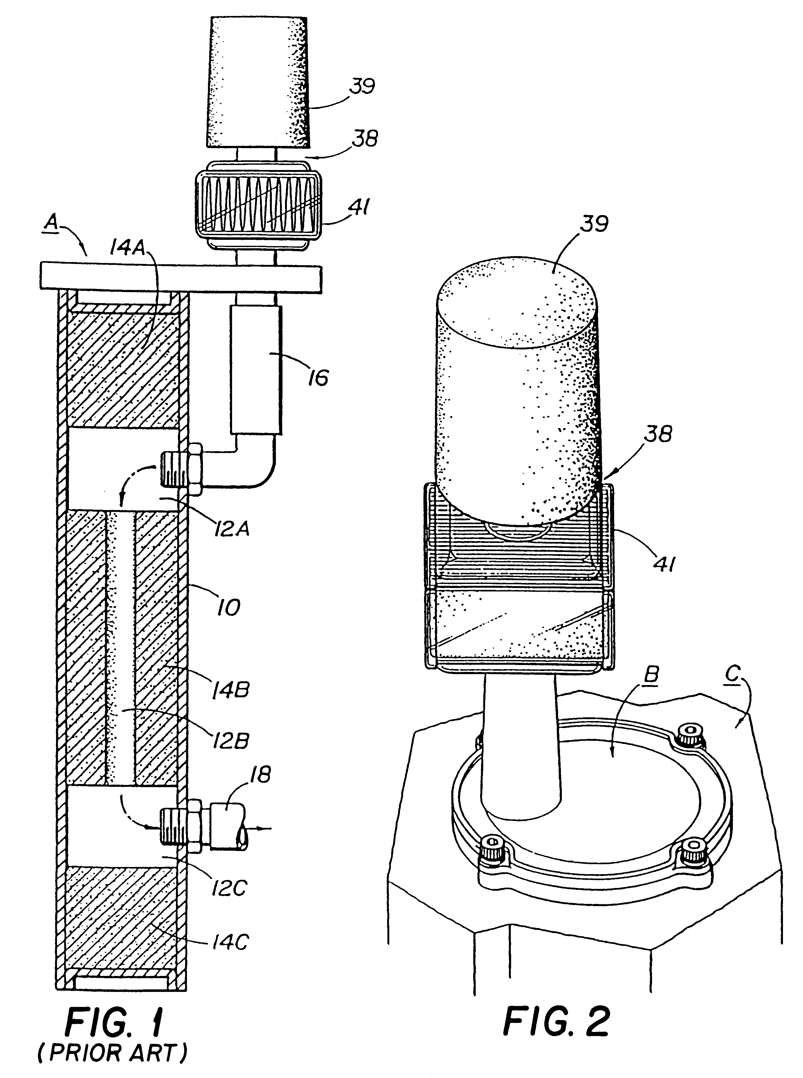
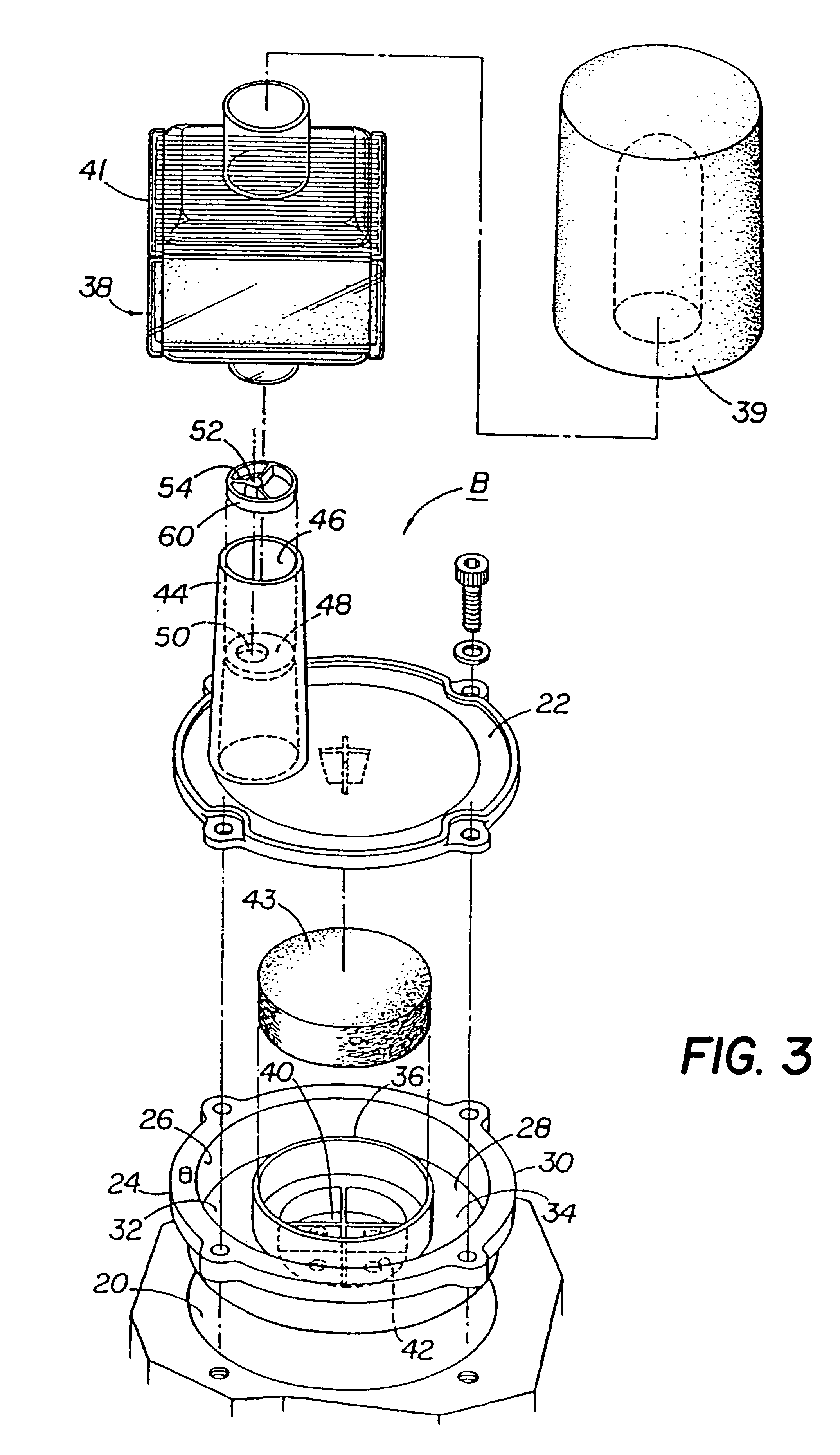
Referring now to the drawings, the present invention will be described in more detail. FIG. 1 illustrates prior art muffler A. Prior art muffler A is designed to be utilized with a standard compressor such as a compressor provided by Thomas Industries of Sheboygen Wisconsin. Prior art muffler A includes cylindrical housing 10 that encloses three chambers 12a, 12b, and 12c that are defined between foam filters 14a, 14b and 14c. Muffler inlet 16 communicates air into the muffler and muffler outlet 18 communicates air from the muffler to the compressor (not shown). This design utilizes several separate components that must be coupled to one another to define the entire muffler. It can be appreciated that the use of multiple, separate components adversely affects the cost of the muffler assembly in that additional materials, such as clamps, flexible hoses, seals and other fixtures, are needed to connect the various components of the muffler to the compressor. In addition, the use of mul...


PUM


Abstract

A muffler assembly for muffling noises associated with a compressor. The muffler assembly is mounted on the compressor such that the two move as a solid body. The muffler assembly includes an intake having a hollow interior adapted to receive a first flow of gas from the ambient environment. A baffle disposed in the hollow interior of the intake restricts the flow of gas through the intake. In one embodiment, the baffle defines at least a portion of a plurality of fluid portals that separate the first flow of gas into a plurality of flows of gas as the gas passes from a first side of the baffle to a second side of the baffle. As a result, the first flow of gas is disturbed and noise from the compressor is thereby attenuated. In another embodiment, a plurality of baffles are disposed in the hollow interior of the intake to define a tortuous path for the flow of gas through the intake for attenuating noise.

Description

1. Field of the InventionThis invention relates to a muffler system in general, and, more particularly, to an integrated muffler system for decreasing the noise level of a compressor and for manipulating the frequency of the soundwaves associated with the operation of a compressor to produce a more tranquil operating environment.2. Description of the Related ArtCompressors are utilized for compressing air or other gas at a low pressure, such as atmospheric pressure, to a higher pressure for subsequent use. One such application is the use of a compressor with an oxygen concentrator, where air is drawn into the compressor from the surrounding environment through an inlet port of the compressor and then compressed and passed through an outlet of the compressor to the molecular sieves of the oxygen concentrator.A compressor includes a housing that houses a connecting rod assembly and a piston assembly which compress the air. The piston assembly generally consists of a compressor head co...

Claims


Application Information

Patent Timeline
Patent Type & Authority Patents(United States)
IPC IPC(8): F04C29/06F02M35/12
CPCF04C29/065F02M35/1272F02M35/1211
Inventor CZABALA, MICHAEL P.MURDOCH, ROBERT W.
Owner RIC INVESTMENTS LLC
Why Eureka
Try Eureka