Muffler structure

a muffler and structure technology, applied in the direction of mechanical equipment, machines/engines, gas passages, etc., can solve the problems of hard to improve the productivity of the muffler and to reduce the cost, and achieve the effect of lowering the cost of the muffler

Inactive Publication Date: 2002-05-28
HONDA MOTOR CO LTD
View PDF4 Cites 61 Cited by
  • Summary
  • Abstract
  • Description
  • Claims
  • Application Information

AI Technical Summary

Benefits of technology

It is, therefore, an object of the invention to provide a muffler structure capable of lowering the cost of the muffler.
Furthermore, because it is unnecessary to joint the butt portion of the punching metal, a metal that is punched with a plurality of holes having open punched holes at both end portions is usable. Therefore, a commercial punching metal may be used after cutting to a predetermined shape, whereby a metal that is punched with a plurality of holes for the inner tube is obtainable at a low cost.

Problems solved by technology

It is, therefore, hard to improve muffler productivity and to lower costs.

Method used


Image

  • Muffler structure
  • Muffler structure
  • Muffler structure

Examples


Embodiment Construction

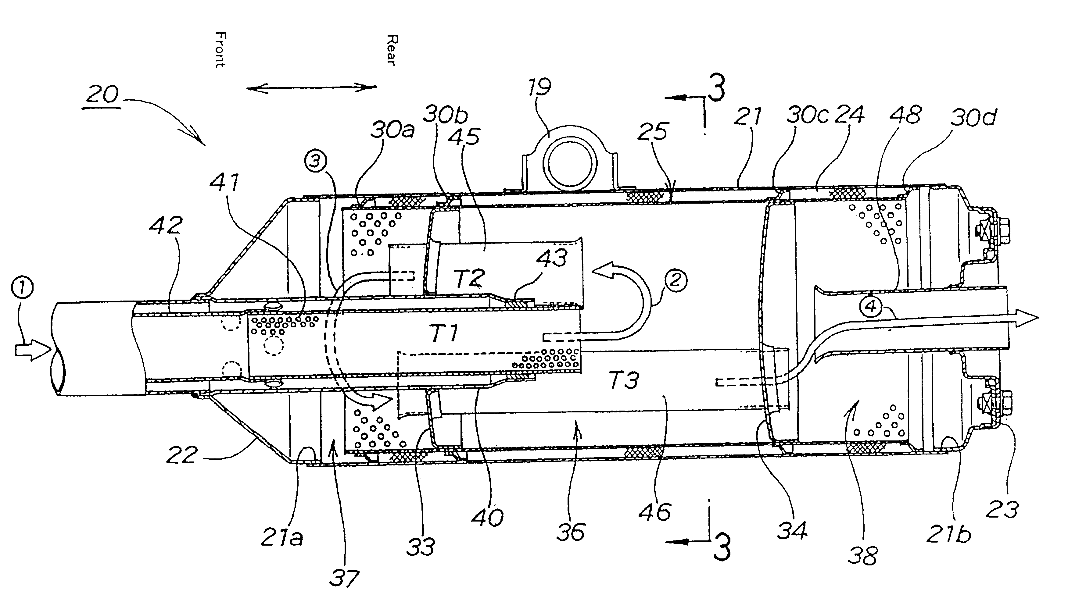
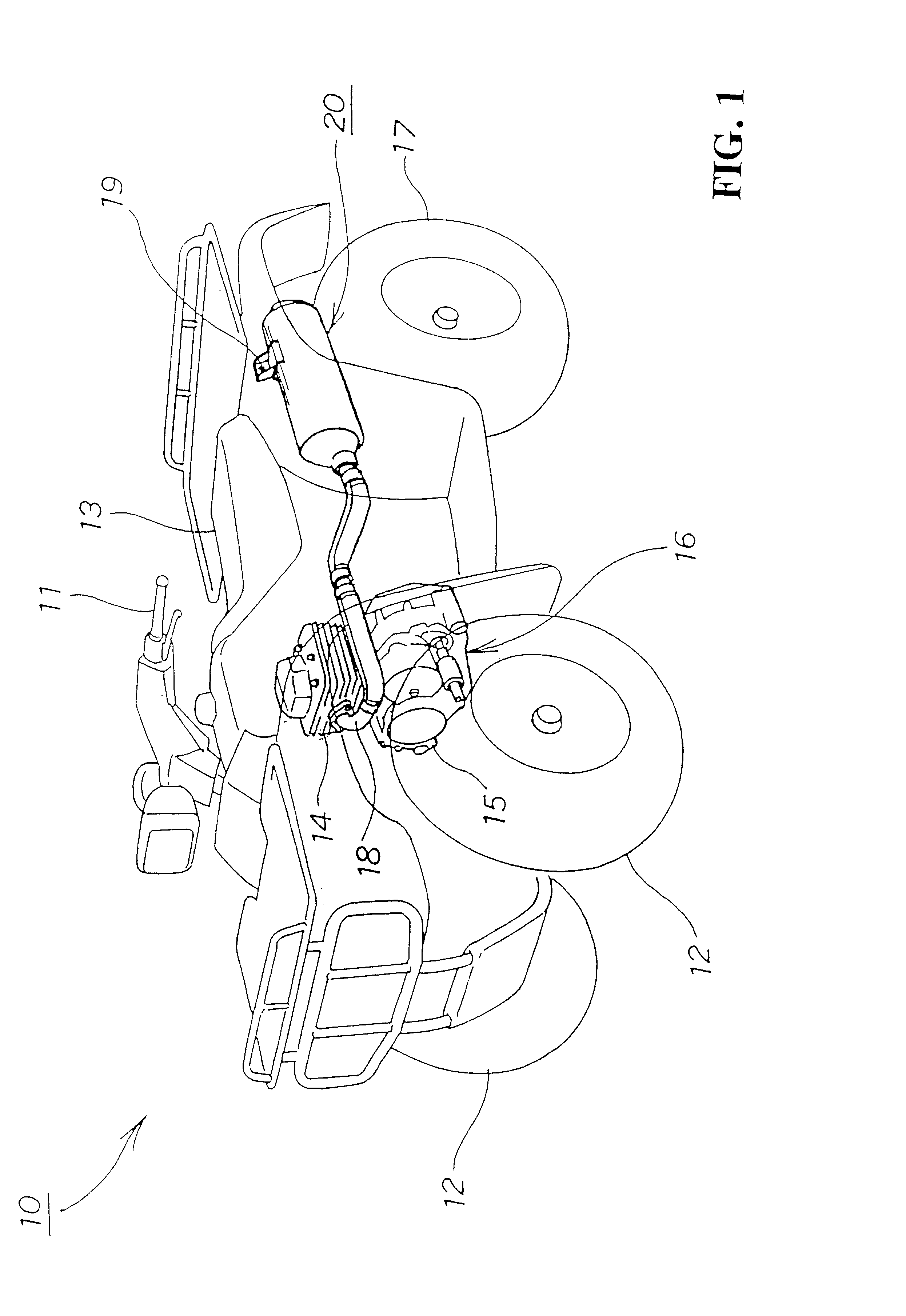
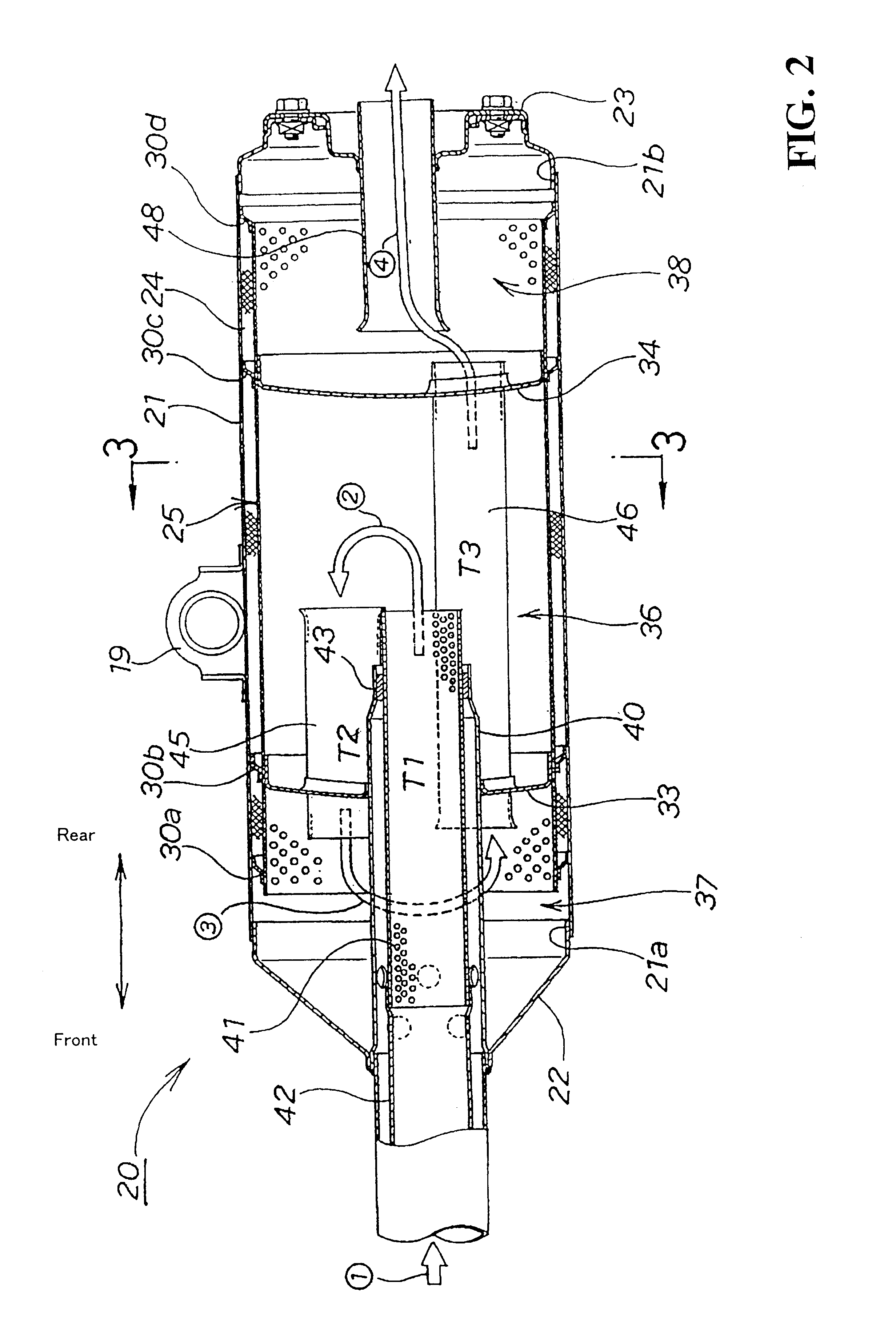
A preferred embodiment of a muffler structure according to this invention will be explained with reference to the accompanying drawings wherein FIG. 1 is a perspective view of an all-terrain vehicle (ATV) equipped with the muffler structure of the present invention.

The ATV 10 comprises a handlebar 11 rotatably mounted on a vehicle frame (not shown), front wheels 12, 12 which are steerable by the handlebar 11, a seat 13 attached on the upper part of the vehicle frame, a power unit 16 including an engine 14 mounted below the seat 13 and a transmission 15, rear wheels 17, 17 (the right rear wheel 17 is not shown) driven together with the front wheels 12, 12 by the power unit 16, an exhaust pipe 18 extends rearwardly from the front of the engine 14. A muffler structure 20 is connected to the rear part of the exhaust pipe 18 and mounted by a mounting bracket 19 on the vehicle frame.

The AMV 10 is a buggy having a compact, light-weight vehicle body, which is easy to operate to be able to m...


PUM


Abstract

To provide a muffler structure capable of lowering muffler cost. A muffler structure is provided in which a sound absorbing material is laid on the inside surface of an outer tube. The sound absorbing material is retained by an inner tube made of a metal that is punched with a plurality of holes. The inner tube is divided into a plurality of expansion chambers. Exhaust gas from an engine is led into the fiat expansion chamber by an inlet pipe. The exhaust gas is discharged out after being supplied to the second and third expansion chambers in succession through the connecting pipes. In the muffler structure, the inner tube is made of an approximately flat metal that is punched with a plurality of holes by bending the metal into circular form until its opposite edges are butted to each other, and is fitted in the outer tube, with the butt portions not jointed, so that the butt portions will come behind the connecting pipe when viewed from the inlet pipe side.

Description

1. Field of the InventionThis invention relates to a muffler structure in which a sound absorbing material is arranged on the inside surface of an outer tube, and is retained with an inner tube made of a metal that is punched with a plurality of holes.2. Description of Prior ArtMufflers for motorcycles are of such a design that a sound absorbing material is installed between outer and inner tubes, and furthermore the interior of the inner tube is divided into a plurality of expansion chambers to deadening an exhaust sound. The muffler will be explained in detail by referring to the following drawing.FIG. 6 is a schematic view of a conventional muffler structure. A sound absorbing material 102 (glass wool) is installed on the inside surface of an outer tube 101 of a muffler 100, and then is retained by an inner tube 103 made of a metal that is punched with a plurality of holes. Exhaust gas from the engine (not shown) is discharged out of the muffler 100 through the inner tube 103 as ...

Claims


Application Information

Patent Timeline
Patent Type & Authority Patents(United States)
IPC IPC(8): F01N1/24F01N1/08F01N13/08F01N13/18
CPCF01N1/084F01N1/24F01N1/089F01N2470/02
Inventor YASUDA, KAZUHIRO
Owner HONDA MOTOR CO LTD
Why Eureka
Try Eureka