Reduced reflectance polarized display

a polarized display and reflectance reduction technology, applied in static indicating devices, instruments, non-linear optics, etc., can solve the problems of affecting the total affecting the overall reflectance of the display, and reducing the residual reflection

Inactive Publication Date: 2002-05-21
HONEYWELL INC
View PDF6 Cites 180 Cited by
  • Summary
  • Abstract
  • Description
  • Claims
  • Application Information

AI Technical Summary

Problems solved by technology

In display applications, it is difficult to maintain high contrast output at high ambient illumination levels.
The multiple layers, however, adversely affect the total reflectance of the display.
However, the suppression of the residual reflection still remains a problem.
While bonding the cover glass 4 to the display is somewhat succes

Method used


Image

  • Reduced reflectance polarized display
  • Reduced reflectance polarized display
  • Reduced reflectance polarized display

Examples


Embodiment Construction

The subject matter of the present invention is particularly suited for use in connection with displays, such as LCDs. As a result, the preferred exemplary embodiment of the present invention is described in that context. It should be recognized, however, that such description is not intended as a limitation on the use or applicability of the present invention, but is instead provided merely to enable a full and complete description of a preferred embodiment.

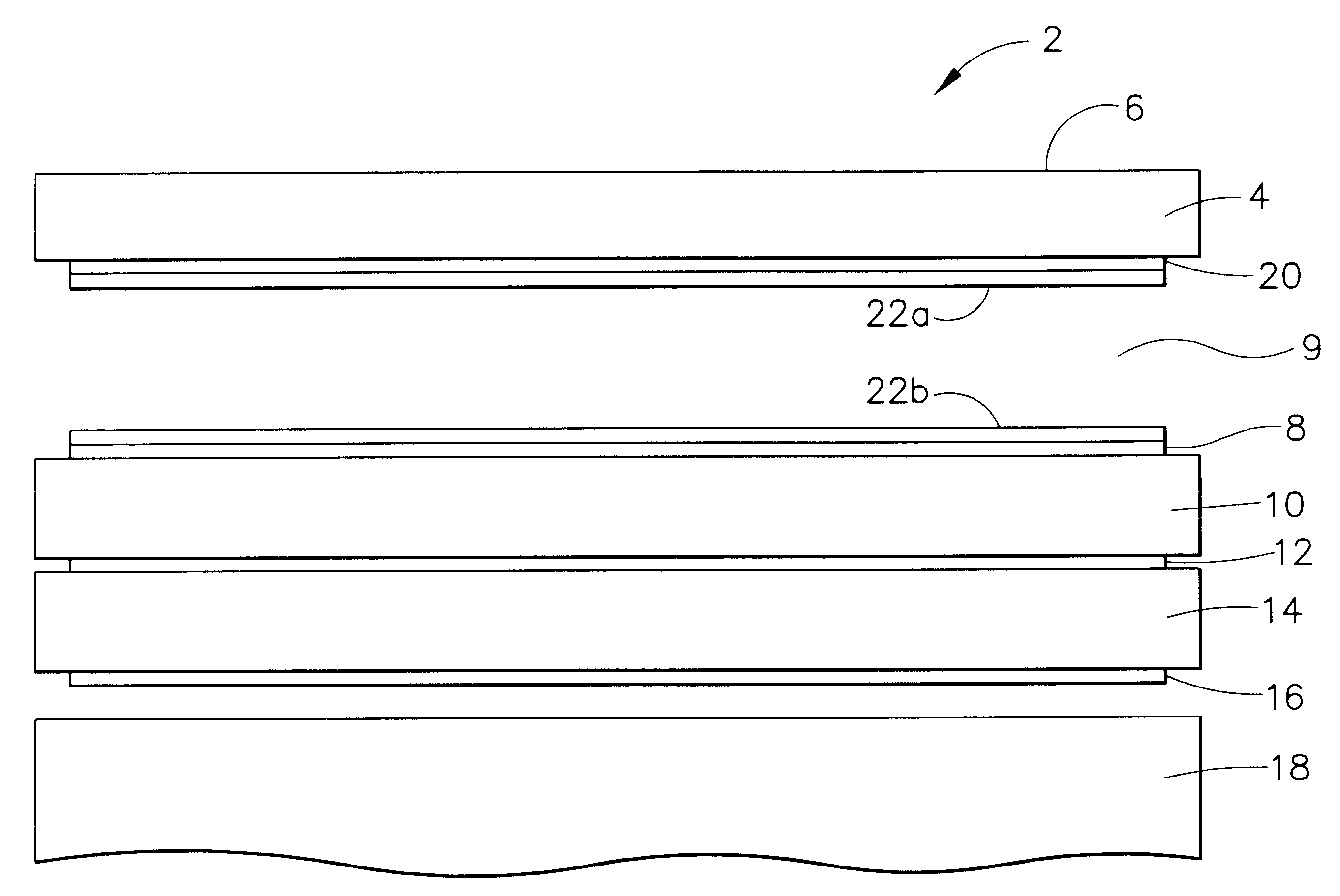
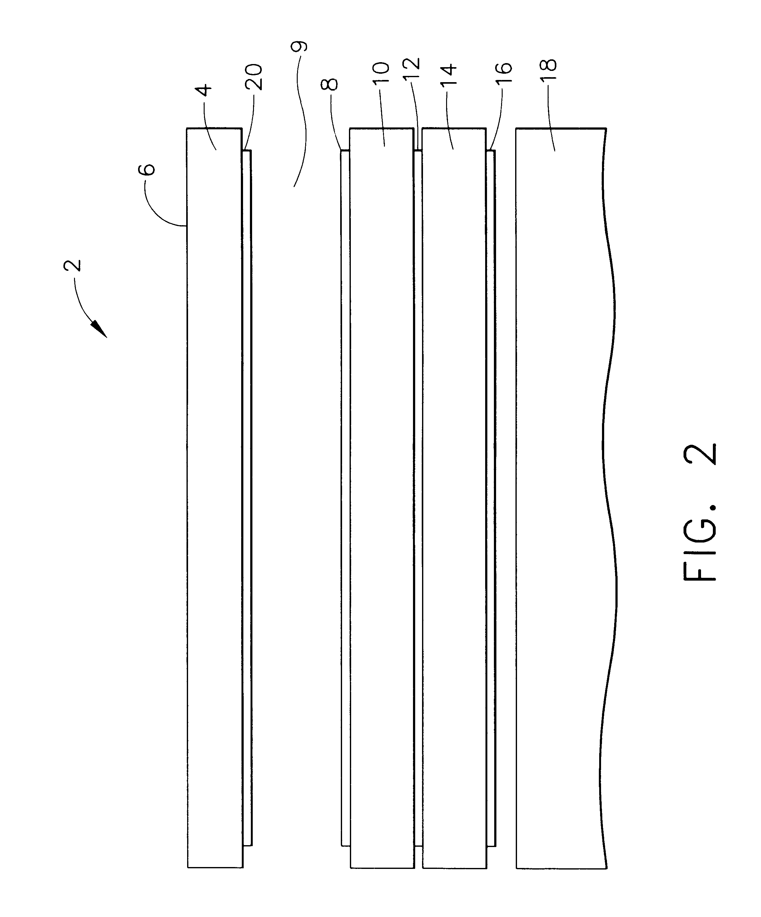
Referring now to FIG. 2, a display 2 according to various aspects of the present invention comprises: a cover glass 4; a front gap 9; a front polarizer 8; a first substrate 10; a liquid crystal layer 12; a second substrate 14; a rear polarizer 16; an auxiliary polarizer 20; and a backlight 18. Each of the components of the display 2 is suitably a conventional LCD component. In particular, the cover glass 4 suitably comprises a conventional cover glass for use in conjunction with LCDs, especially high contrast LCDs, to protect the...


PUM


Abstract

A method and apparatus according to various aspects of the present invention provides a polarized display exhibiting reduced reflectances. A polarizer is disposed adjacent to a cover glass in front of the display. Light intended to be transmitted by the display is transmitted by the polarizer. Light reflected after passing through the polarizer reverses polarization, and is absorbed as it intercepts the polarizer following reflection.

Description

1. Field of the InventionThe invention relates to displays, and more particularly, to methods and apparatus for reducing unwanted reflections in displays.2. Description of the Related ArtIn display applications, it is difficult to maintain high contrast output at high ambient illumination levels. However, polarized light displays and active matrix liquid crystal display (AMLCD) flat panels work well in maintaining the contrast in their displays because light passes through several absorbing layers before reflecting or scattering back out from the light producing mechanism. The multiple layers, however, adversely affect the total reflectance of the display. Even though the reflectance at layer boundary in itself may be quite small, the sum of the reflections may be significant.Referring to FIG. 1, a conventional polarized display 2, such as a liquid crystal display (LCD), includes a cover glass 4 having an antireflective coating 6. A front polarizer 8, a first substrate 10, a liquid ...

Claims


Application Information

Patent Timeline
IPC IPC(8): G02F1/1335G02F1/13G02F1/13357G02F1/13363
CPCG02F1/133502G02F1/133528G02F2201/16G02F2001/133638G02F1/133638
Inventor LARSON, BRENT D.HAIM, ELIAS S.
Owner HONEYWELL INC
Why Eureka
Try Eureka