Ball pitching apparatus-3

a technology of pitching apparatus and ball, which is applied in the direction of weaponry, friction-wheel launchers, white arms/cold weapons, etc., can solve the problem of relativly short central shaft of motor shaft, and achieve the effect of more lateral spin and more lateral curves

Inactive Publication Date: 2002-06-11
SPORT SCI
View PDF4 Cites 19 Cited by
  • Summary
  • Abstract
  • Description
  • Claims
  • Application Information

AI Technical Summary

Benefits of technology

It is an object of this invention to disclose a ball pitching apparatus having ball grips positioned to match a grip used by a pitcher. A top side portion of the ball is held by two grips; the other side portion of the ball is held by a single grip. A baseball is not quite spherical. The seams on the leather casing extend outwardly from its spherical inner portion approximately 1 / 8". When a pitcher grips a ball he holds the ball only with his index finger, his long finger, and his thumb. He aligns the end portions of his fingers over and behind the seams to better spin the ball so that its trajectory is curved. The three point grip best holds and supports a non spherical ball. If the ball is squeezed more tightly between his long finger and his thumb than between his index finger and his thumb, it will have more lateral spin. The resulting pitch will have more lateral curve.
It is an object of this invention to disclose an apparatus which will grip and squeeze marginally varying diameters of balls with uniform force. Different baseballs have different coverings and seams, used balls are softer than new balls, and diameters of gripped and squeezed balls may vary as much as 1 / 10". When one considers that the ball must be accelerated to as much as 100 mph in a brief 50 milliseconds as it passes and slips between two fast spinning wheels, how hard it is squeezed, and how much it slips, is critical to its acceleration. A mechanism which automatically squeezes balls of varying diameters with consistent force can accommodate and uniformly pitch new and used balls, as well as balls having different seam and overall dimensions consistently with adequate accuracy. This is a significant practical advantage.
It is yet a further object of this invention to disclose a baseball pitching apparatus which utilizes wheels having brushless internal DC drive motors. These motors may be more accurately controlled for speed than DC motors having brushes. Additionally, this arrangement loads a relatively short motor shaft centrally. Compared to a cantilevered loading arrangement the motor shaft and bearings may be much lighter and still adequately support repeated and substantial loading moment as balls are instantaneously accelerated to as much as 100 mph.
It is a final object of this invention to disclose a ball pitching which may not only more accurately pitch strikes, but which can pitch strikes having varying positions within the strike zone. With the use of a microprocessor which memorizes and controls different frame rotational positions, as well as wheel rotational speeds, it is possible to replace multiple pitching machines, each used to throw substantially different pitches, with a single machine.
Yet another aspect of this invention, in a pitching apparatus as described above, provides for the improvement comprising: wheel drive means which are DC motors internally positioned within the wheel so that the shafts and bearings in the motors are directly and radially loaded when the ball is gripped and accelerated and so that the frame, shafts, and bearings may be substantially lighter than if they need be designed to maintain the wheels in precise rigid alignment while bearing a repeated cantilevered load arising from the ball's acceleration. This results in a lighter and more compact frame head, which in turn facilitates portability, and rotational movement and control of the frame head on the stand.

Problems solved by technology

Additionally, this arrangement loads a relatively short motor shaft centrally.

Method used


Image

  • Ball pitching apparatus-3
  • Ball pitching apparatus-3
  • Ball pitching apparatus-3

Examples


Embodiment Construction

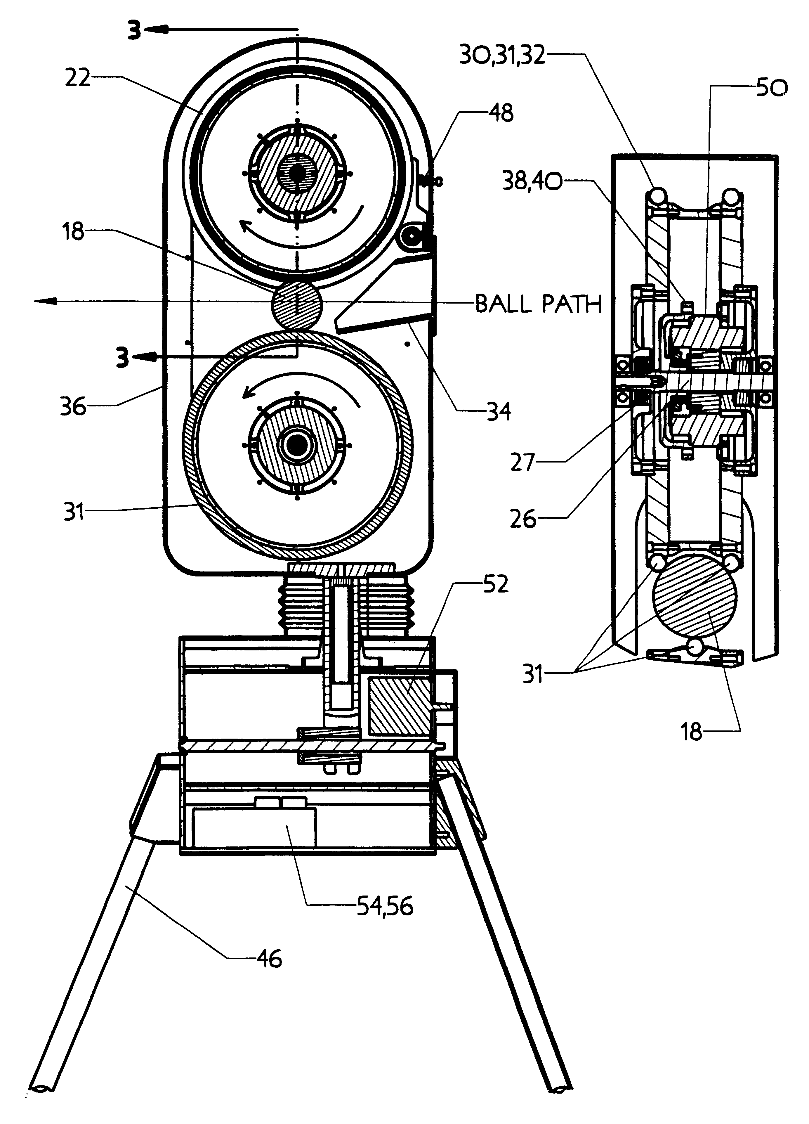
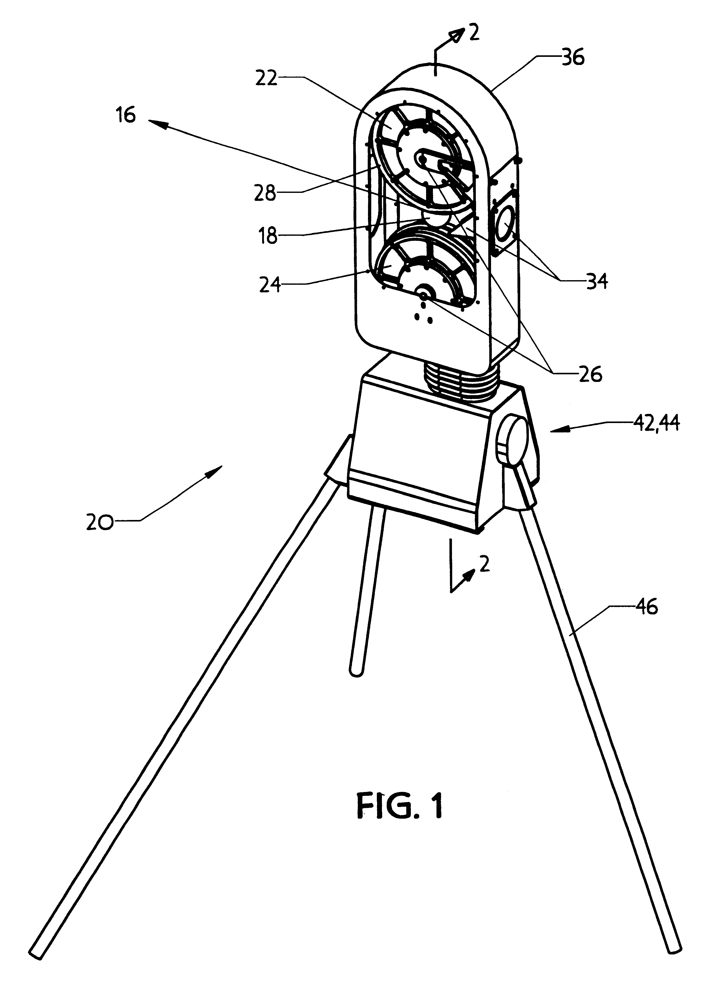
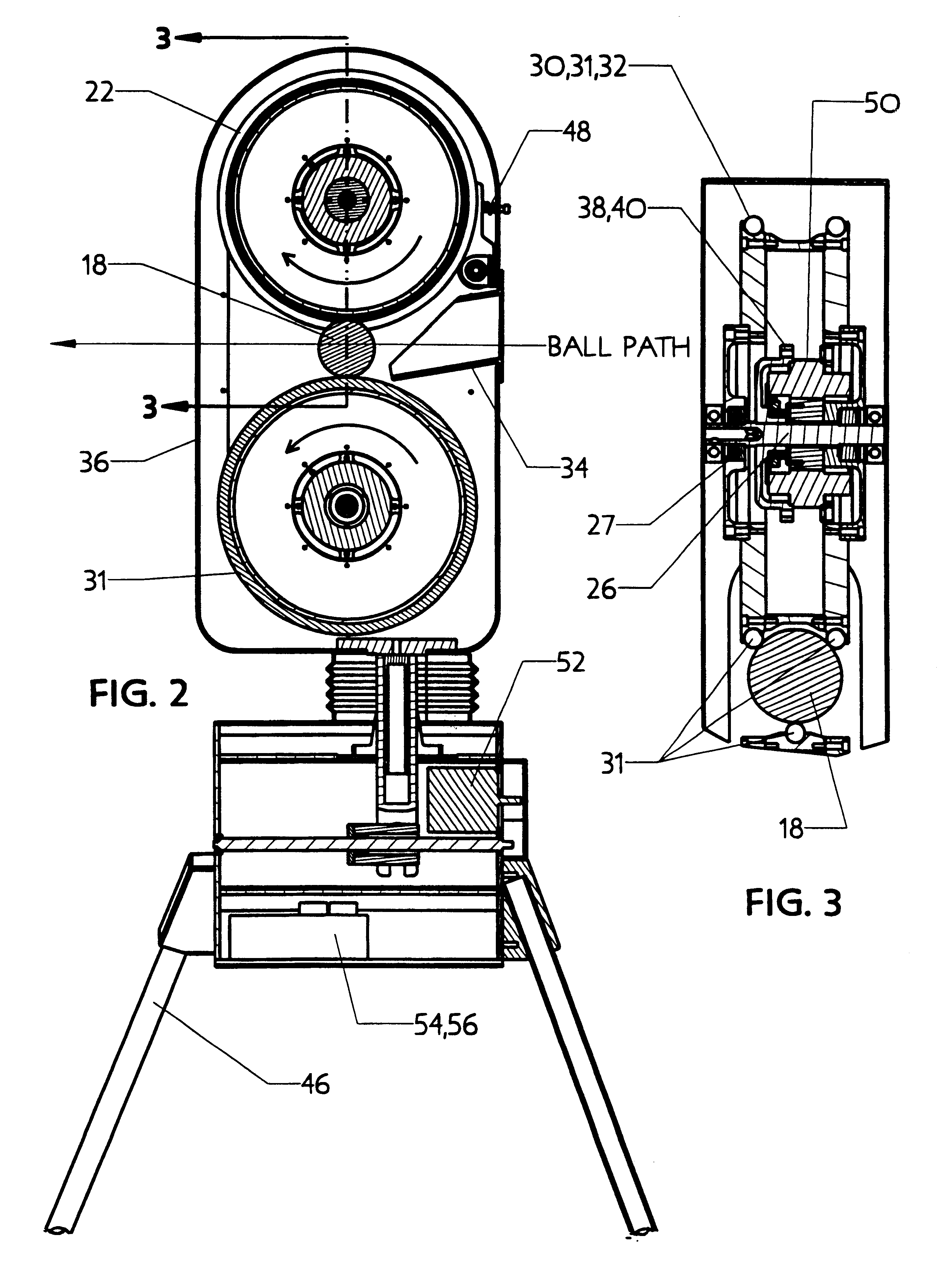
Turning now to the drawings and more particularly to FIG. 1 we have a perspective view of a ball pitching apparatus 20. The apparatus 20 for pitching a ball 18 is of the type comprising: an upper wheel 22 and a lower wheel 24, said wheels 22,24 rotating on substantially parallel shafts 26 and having generally aligned and spaced rims 28 carrying peripheral ball gripping means 30. Each of the wheels 22,24 have independent speed controls 42,44 and drive means 38 for rotation in opposite directions at different selected speeds. A ball feeder 34 for feeding the ball 18 between the rims 28 allows the ball 18 to be gripped between the rims 28 and accelerated in a trajectory 16 generally tangential to the points on the rims 28 it is gripped between. A head frame 36 carries the wheels 22,24, drive means 38, and ball feeder 34. A stand 46 carries the head frame 36.

One improvement to the ball pitching apparatus 20 comprises: a singular gripping band 31 on the lower wheel 24 and two spaced grip...


PUM


Abstract

An improved ball pitching apparatus for a ball pitching machine of the type having an upper and lower wheel, said wheels rotating on substantially parallel shafts and having generally aligned and spaced rims carrying peripheral ball gripping bands; independent speed controlled drive motors; a ball feeder for feeding the ball between the spaced rims so that the ball will be gripped and accelerated in a trajectory tangential to the rims; a head frame carrying the wheels, drive motors, and ball feeder; and, a stand carrying the head frame. The improvements comprise: 1) a singular gripping band on one wheel and two spaced gripping bands on the other wheel so that the ball contacts and is gripped by three discrete points on its peripheral surface; 2) one of the wheels rotating on a shaft biased towards the other wheel so that the ball to be pitched will be gripped with a similar force regardless of diameter variations; and, 3) wheel drive DC motors internally positioned within the wheel so that the shafts and bearings in the motors are directly and radially loaded when the ball is gripped and accelerated. Internally driven wheels facilitate microprocessor and programmed memory control of a servo motors to control rotation of the head frame on the stand. This arrangement enables quick and precise adjustment to different pitching positions.

Description

This invention relates to baseball pitching machines. More particularly this invention relates to an improved pitching machine having ball grips positioned to match a grip used by a pitcher. A top side portion of the ball is held by two grips; the other bottom side portion of the ball is held by a single grip. This arrangement facilitates laterally spinning a ball; and coupled with a floating wheel which more consistently squeezes varying ball diameters, results in a ball pitching apparatus which can throw varying pitches more consistently within the strike zone.U.S. Pat. No. 4,197,827 issued to T. L. Smith on Apr. 15, 1980 discloses a ball pitching apparatus which utilizes a spinning upper and lower wheel. Each wheel utilizes an elastomer peripheral concave surface to grip a ball which is accelerated when it is passed between the spinning wheels. The ball is accelerated to 60 plus mph in approximately 50 milliseconds as it passes between the wheels. One problem with the apparatus i...

Claims


Application Information

Patent Timeline
Patent Type & Authority Patents(United States)
IPC IPC(8): A63B69/40F41B4/00
CPCA63B69/406F41B4/00A63B2069/402
Inventor CALDWELL, MARCUS L.
Owner SPORT SCI
Why Eureka
Try Eureka