Tine structure for bare root tree and stump extracting tool

a technology for removing stumps and trees, applied in the field of tools for removing arborescent materials, can solve the problems of damage or destruction, damage to the overall biological system of the removed plant, and the traditional digging tools of mechanical earth moving equipment such as buckets, shovels and the like are not particularly effective in plant extraction, etc., and achieves substantial rigidity and strength of connection, simple and easy fastening and release of tines

Inactive Publication Date: 2002-06-11
BOUCHARD JOHN M
View PDF17 Cites 11 Cited by
  • Summary
  • Abstract
  • Description
  • Claims
  • Application Information

AI Technical Summary

Benefits of technology

The modified bare root plant extractor provides a peripherally defined frame having structure for mounting on the tool connecting plate of an earth moving vehicle for transport and adjustable vertical and tilting motion. The frame provides an elongate laterally extending lower horizontal tine beam releaseably carrying a plurality of laterally spaced extracting tines extending forwardly from individual releaseable mounting structures. One or more of the extracting tines carry one or more vertically depending fins to provide strength and direct tine motion in a horizontal plane upon passage through the earth; one or more extracting tines carry one or more horizontal fins to direct tine motion in a vertical plane upon passage through the earth and provide support for earth and root material thereabove. One or more extracting tines carry one or more soil retaining plates to support earth and plant material thereabove.
A still further object is to provide such a tool that is of new and novel design, of rugged and durable nature, of simple and economic manufacture and one otherwise well suited to the uses and purposes for which it is intended.

Problems solved by technology

This method of extracting, transporting and merchandising trees, shrubs and other larger plants normally removes substantial amounts of the peripheral and tap root systems of the plants and may cause disruption of the overall biological systems of removed plants with resultant shock-type reactions that may be sufficient to kill the plants over a period of time, if not immediately, or to substantially lessen their viability.
Though bare root type extraction, especially of larger nursery stock, has increased in the recent past, it probably is not and has not been so extensively used as balled root extraction largely because of the difficulties involved in the bare root extraction process and the lack of specific mechanical apparatus to efficiently and effectively accomplish it.
Traditional digging tools of mechanical earth moving equipment such as buckets, shovels and the like are not particularly effective in plant extraction as these tools tend to shear the earth where they enter it and this action also tends to shear or otherwise damage root structure in the path of the digging device to damage or destroy substantial amounts of that root structure in and outwardly of the digging area.
This process has not proven particularly effective because, at the time of pulling, the peripheral root structure commonly is widespread, relatively delicate and substantially embedded in the surrounding earth.
By reason of the comparatively low tensile strength of the peripheral root systems of plants and the nature of their earth embedment, substantial portions of the peripheral roots are damaged or severed from a plant removed in this manor.
The addition of horizontal fins tends to somewhat increase the vertical cross-sectional area of the extracting structure and this increases the force necessary to insert the extracting structure through the earth.

Method used


Image

  • Tine structure for bare root tree and stump extracting tool
  • Tine structure for bare root tree and stump extracting tool
  • Tine structure for bare root tree and stump extracting tool

Examples


Embodiment Construction

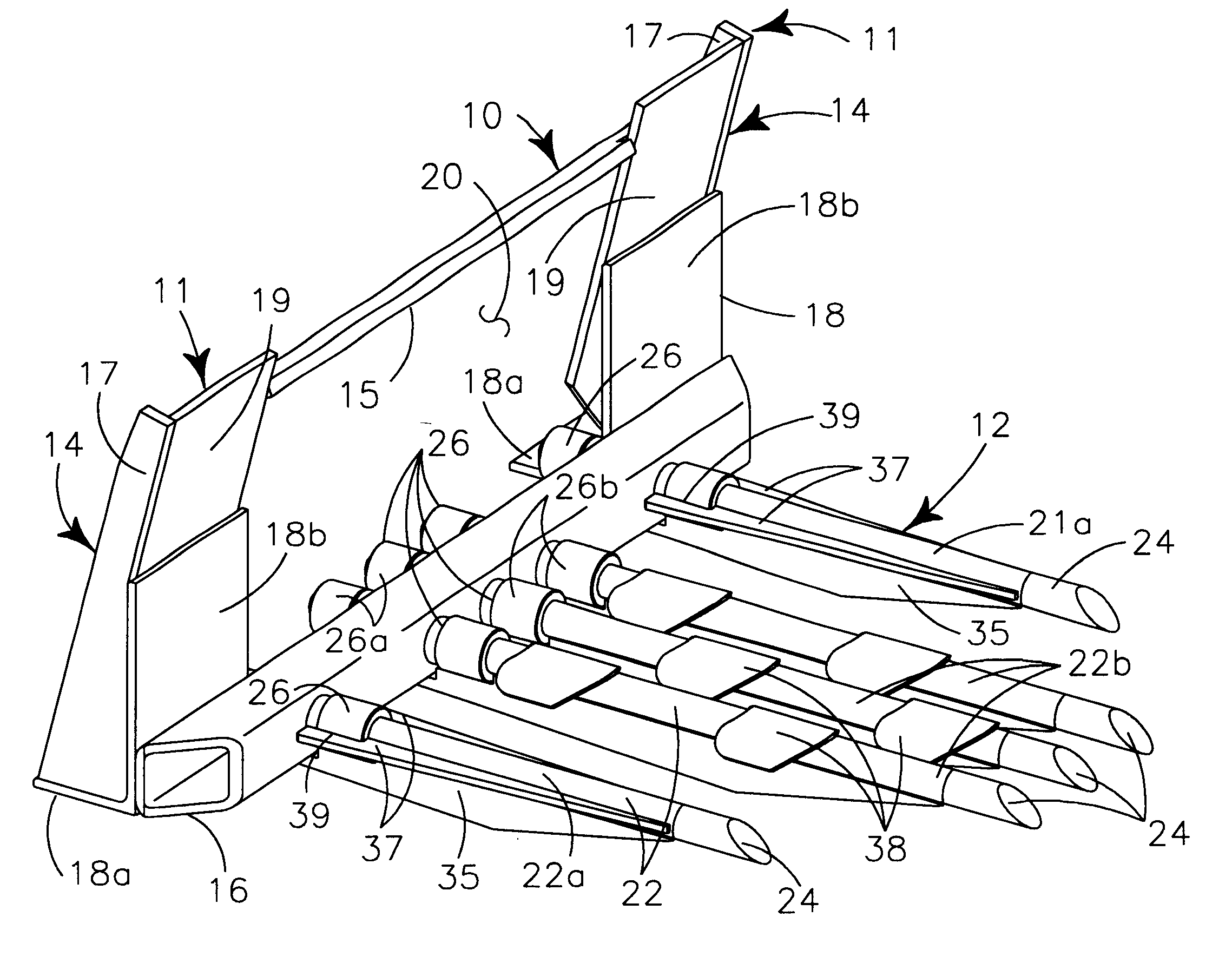
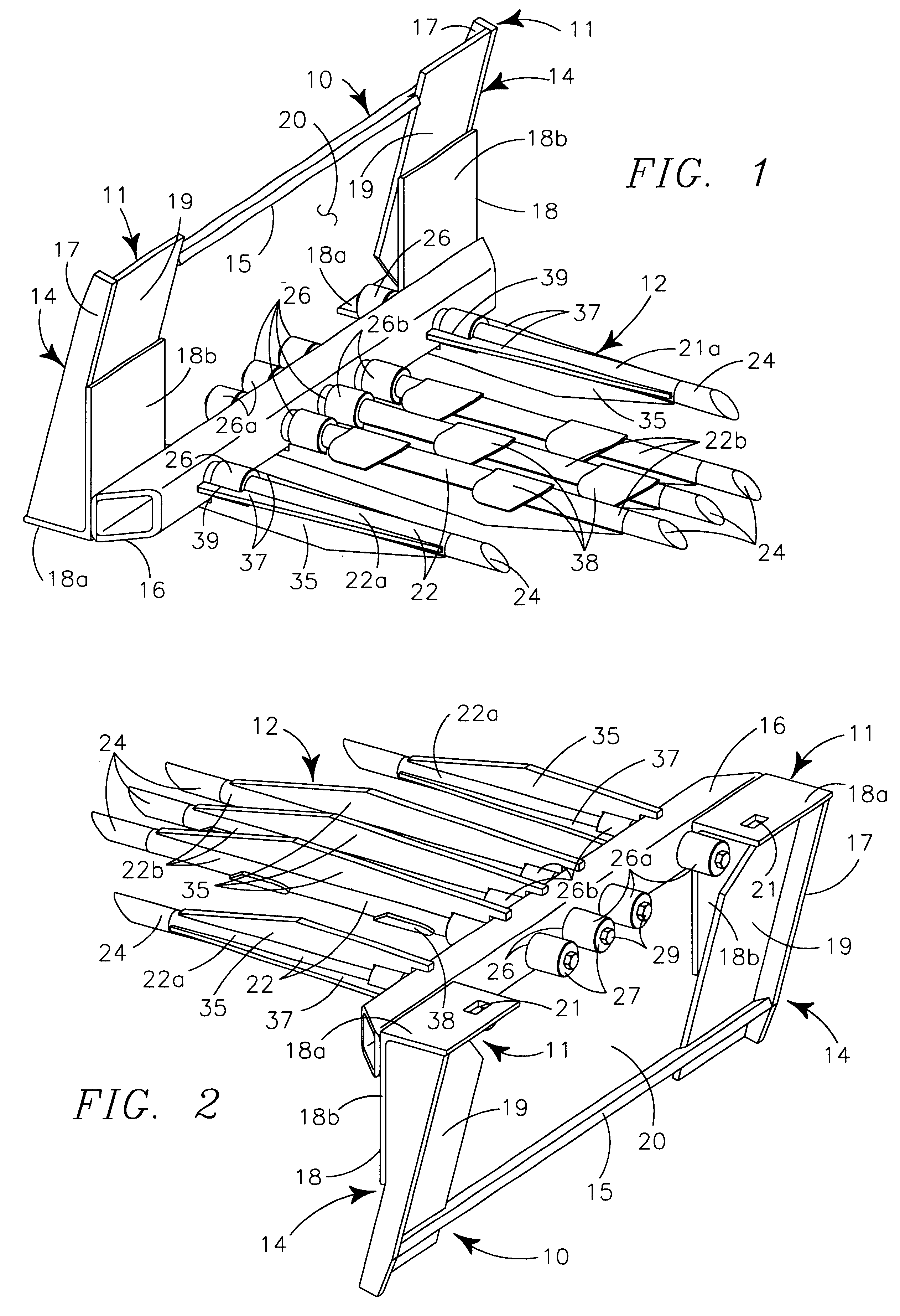
Referring to FIGS. 1 and 2, it is seen that the tool generally provides frame 10 carrying connection structure 11, for interconnection with the tool connection plate of powering vehicle 13, and extracting structure 12 extending forwardly from the frame.

Frame 10 provides similar sides 14 interconnected in their upper portions by upper horizontal beam 15 and in their lowermost portions by lower tine beam 16. Both upper horizontal beam 15 and lower tine beam 16 are box-type beams with the tine beam having a larger cross-sectional size to provide appropriate strength and rigidity and a configuration adaptable to allow interconnection of tines therein. The sides 14 are mirror images of each other, each formed by vertical planar side plate 17 structurally carried by L-shaped angled bottom element 18 having lowermost bottom plate 18a and upstanding fastening arm 18b configured to structurally interconnect with the lower forward facing edge of the adjacent side 17. The fastening arm 18b has...


PUM


Abstract

A tool, for mounting on a powering vehicle for transport, vertical motion and pivotal motion about a horizontal axis, provides a frame having connecting structure to interconnect with the powering vehicle. The frame carries extracting structure having plural laterally spaced extracting tines extending forwardly from the lower frame portion. At least one extracting tine has at least one depending vertical fin to increase tine strength and direct tine motion in a horizontal plane upon insertion through the earth; at least one extracting tine has at least one laterally extending horizontal fin to increase tine strength and direct tine motion in a vertical plane upon insertion through the earth; and at least one extracting tine has at least one soil retaining plate to aid support of material thereabove. The fins and plates tend to separate earth above and below the course of their insertion.

Description

BACKGROUND OF INVENTION1. Field of InventionThis invention relates generally to a tool for removing arborescent material from the earth and more particularly to a removable tine structure for the tool that provides support for the removed root and earth structure and partial severance of that structure from earth structure below the tine structure during removal.2. Background and Description of Prior ArtAs the extraction of larger nursery stock has developed and progressed, especially from manual to mechanical methods, two different processes for extraction and preservation of the viability of the stock from the time of extraction to reestablishment in the earth have developed, the first being the "balled root" process and second being the "bare root" process.The bare root mechanical extraction process is the older probably because of its similarity to previously existing manual extraction methods, but the most recent mechanical process to establish economic viability in the modern ...

Claims


Application Information

Patent Timeline
Patent Type & Authority Patents(United States)
IPC IPC(8): A01G23/00A01G23/06
CPCA01G23/062
Inventor BOUCHARD, JOHN M.
Owner BOUCHARD JOHN M
Why Eureka
Try Eureka