Line and pole, travel size fitness device, for upper and lower body weightlifting type physical exercises, utilizing a human's own bodyweight

Inactive Publication Date: 2002-06-11
ANAGNOSTOU THOMAS
View PDF16 Cites 20 Cited by
  • Summary
  • Abstract
  • Description
  • Claims
  • Application Information

AI Technical Summary

Problems solved by technology

However, these facilities require numerous equipment that take space, amount to a lot of weight, and they represent a good deal of monetary investment.
However, home training centers are still costly, have a significant weight and their transportation would require special effort along with assembly and disassembly of several parts.
However, non-gravity media does not feel natural to the human body.
Furthermore, by virtue of simplicity, there is compromise in function.
These devices are often limited, specializing to only certain muscle groups, while failing to provide training for other parts of the body.
However, such equipment retain a plurality of moving parts and linkages due to their geometry, and although portable are not suited to carry-on.
However, there is a plurality of moving components, a fairly involved construction and an overall size that make this device not suitable for traveling standards.
U.S. Pat. No. 06,086,521 offers a more simplistic design, but it is not versatile enough to offer a comprehensive full body workout for a dedicated athlete.
Furthermore, this design is still not compact enough to be considered a handheld device that fits within a travel bag.
Extremely portable devices have limited potential, while those that have extensive weight training potent

Method used


Image

  • Line and pole, travel size fitness device, for upper and lower body weightlifting type physical exercises, utilizing a human's own bodyweight
  • Line and pole, travel size fitness device, for upper and lower body weightlifting type physical exercises, utilizing a human's own bodyweight
  • Line and pole, travel size fitness device, for upper and lower body weightlifting type physical exercises, utilizing a human's own bodyweight

Examples


Embodiment Construction

Overview (FIGS. 1,2,3,4,5)

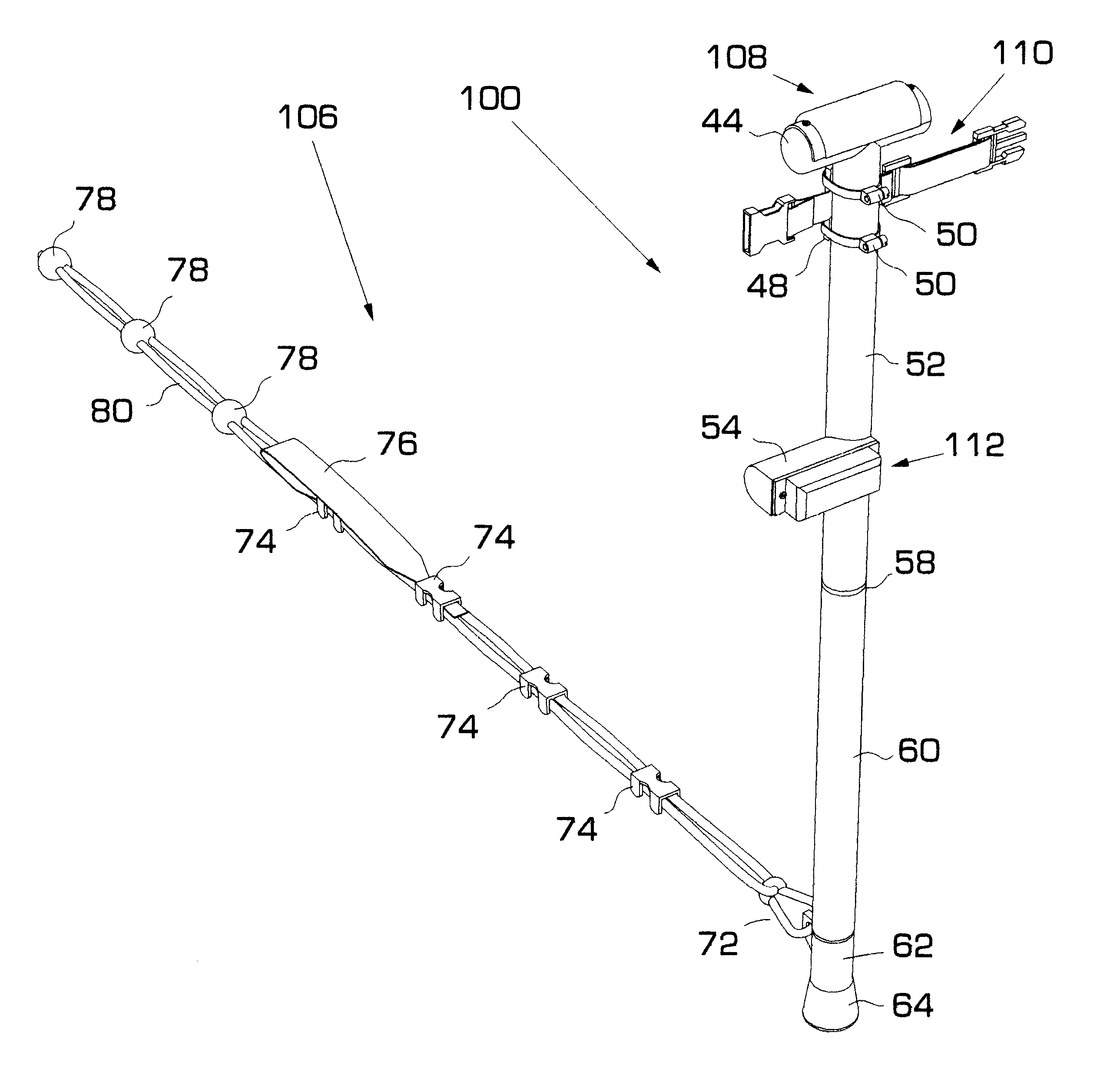
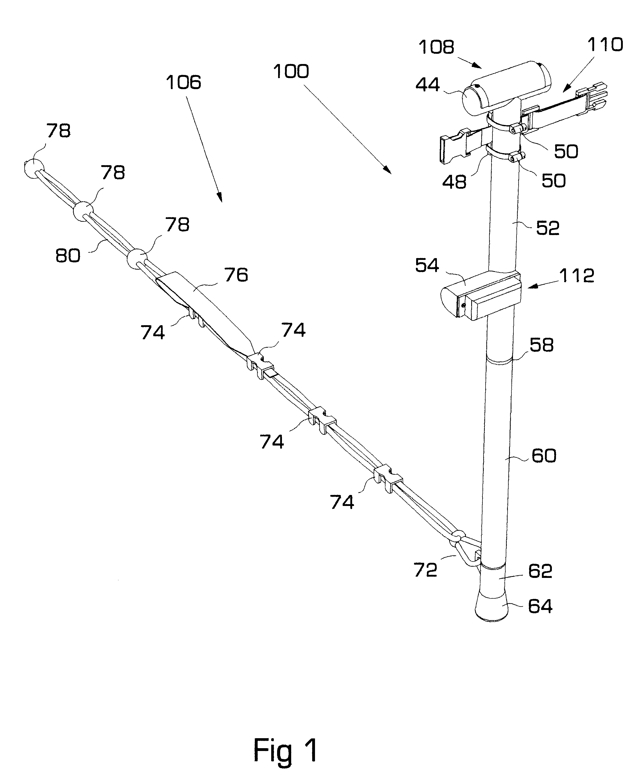
A fully assembled preferred embodiment of the proposed exerciser is shown in FIG. 1. A matching pair (not shown), which is a mirror image of that in FIG. 1, would complete the set or pair to achieve the intended functionality. In the following text, the term exerciser refers to what is shown in FIG. 1. The components are then duplicated to produce a mirror-replica.

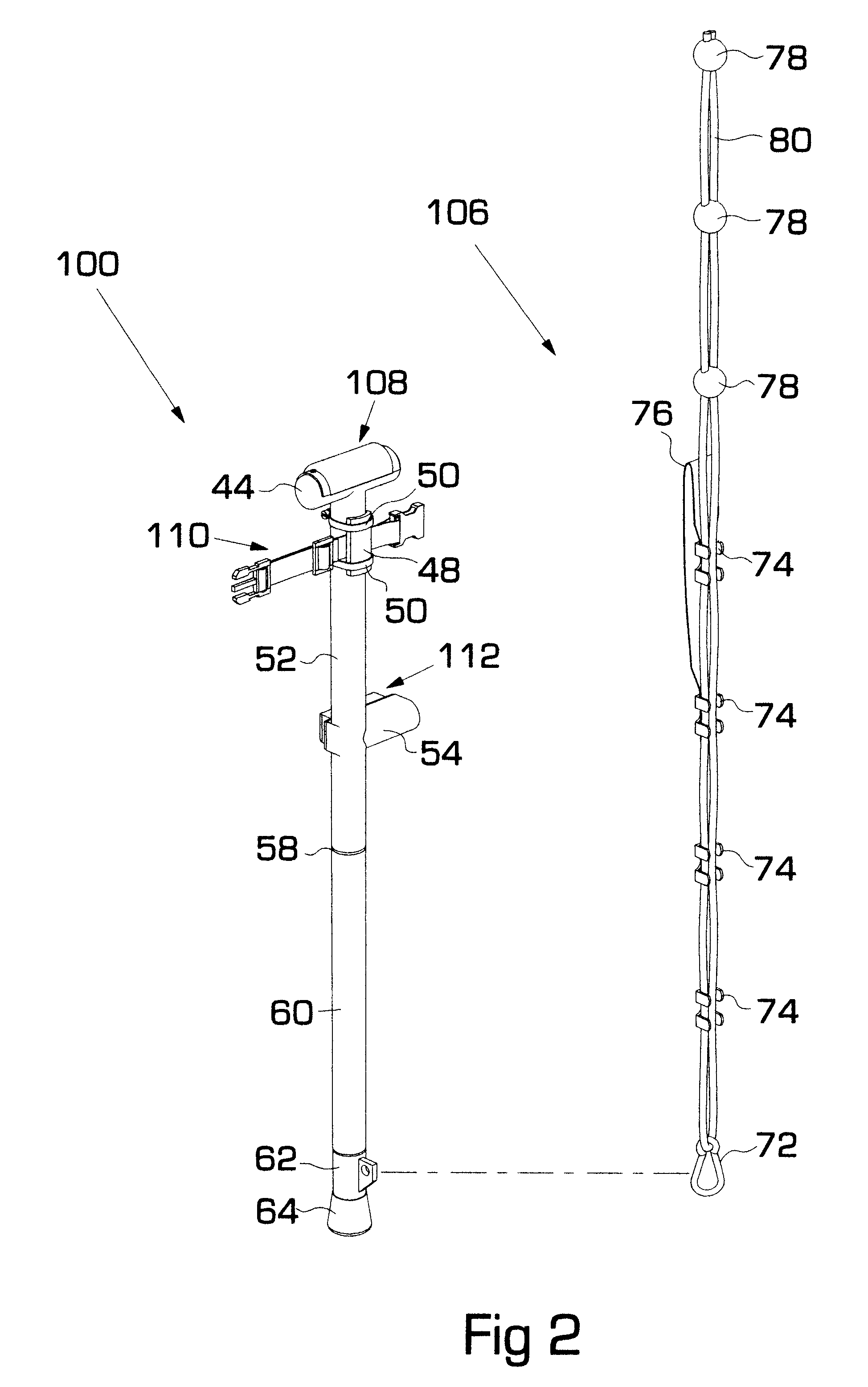
The first component is namely a pole, or rigid-member assembly 100 with an overall length of about 130 cm. Rigid member 100 consists of a primary cushion subassembly 108, an ankle strap subassembly 110, a knee-support subassembly 112 and parts 44 through 70. Parts 66, 68 and 70 are internally located and therefore not visible in FIG. 1.

The second component is a foot restraining tether or namely a traction-member assembly 106 consisting of parts 72 through 80. The overall length of traction-member 106 is about 193 cm long or 1.5 times the length of rigid-member 100.

Rigid member 100 and traction mem...


PUM


Abstract

A travel-size exercise device used in pairs to induce muscle-building effect on both upper and lower body comprising an elongated length-reducible rigid member (100) attached to an elongated flexible foot traction member (106). A set of holding provisions comprise a primary handle (44) forming a T-connection due-top on rigid member (100), and an auxiliary handle (54) forming a perpendicular protrusion midwards on member (100). A set of limb-fastening provisions comprise an ankle strap (110) mounted at right angles upwards on rigid member (100), and a corresponding knee support (112) layered upon auxiliary handle (54). Rigid member.(110) has a bottom end engaged to a revolving shoe (62) removably capped with a friction-tip (64) for stable ground engagement. A traction member (106) has one end comprising a spring clasp (72) attached to shoe (62) of rigid member (100), and an intermediate section comprising a foot strap (76) followed by an array of bumps (78) equidistantly spaced thereafter towards the other end. An operator selectably interfaces with the device, so that enough ground reaction force is transferred through a pair of rigid members (100) to oppose body-weight displacement induced by repetitive motion of the operator's arms or legs.

Description

Not applicableNot applicableREFERENCE TO MICROFICHE APPENDIX Not applicable1. Field of the InventionThis invention relates to weight resistance exercise devices, specifically to those devices that provide full body training, as well as those that are portable and compact enough to be suitable for travel.2. Description of Prior ArtThe observable effect of muscular performance is motion, and evidently it constitutes the key element of exercise. Hence, any ability to sustain motion to the effect of displacing either external objects, or ones' own body, would indicate the level of a person's fitness.Athletes of every kind have begun to realize the importance, effectiveness, and benefits of resistance training, specifically weightlifting, towards improving their performance. The popularity of weightlifting is reasonably expected due to the fact that it feels more natural, compared to other forms of resistance training, such as those involving elastic mediums. An explanation of such prefe...

Claims


Application Information

Patent Timeline
IPC IPC(8): A63B21/068A63B21/06
CPCA63B21/0004A63B21/068A63B21/00047A63B2210/50A63B2023/006
Inventor ANAGNOSTOU, THOMAS
Owner ANAGNOSTOU THOMAS
Why Eureka
Try Eureka