Expandable joint connector

a joint connector and expandable technology, applied in the direction of hose connection, cable termination, borehole/well accessories, etc., can solve the problems of affecting the sealing effect of the pipe, and affecting the sealing effect of the pin and box structur

Inactive Publication Date: 2002-06-25
ENVENTURE GLOBAL TECH LLC
View PDF38 Cites 342 Cited by
  • Summary
  • Abstract
  • Description
  • Claims
  • Application Information

AI Technical Summary

Problems solved by technology

The radial expansion of a conventional connection may also weaken or otherwise damage the pin and box structure sufficiently to permit mechanical separation.
In each case, following the expansion of the pin and box, the pin and box members radially separate, causing the seals to fail.
The separation and distortion following the expansion process compromises the seals located between the pin and box and creates an obstruction in the bore of the pipe.
The distortion can be so great that the pin and box threads may also disengage.
A related cause of the failure of expanded connections is that the radial expansion of a conventional casing joint connection produces different degrees of permanent deformation in the pin and box.
Radial expansion of conventional connectors may also permit the connectors to leak.
Connectors that employ an elastomeric, annular seal ring between the engaged surfaces of the pin and box are also subject to leakage when the connection expands radially.
Subsequent radial expansion of the engaged connection changes the radial compression of the annular seal ri

Method used


Image

  • Expandable joint connector
  • Expandable joint connector
  • Expandable joint connector

Examples


Embodiment Construction

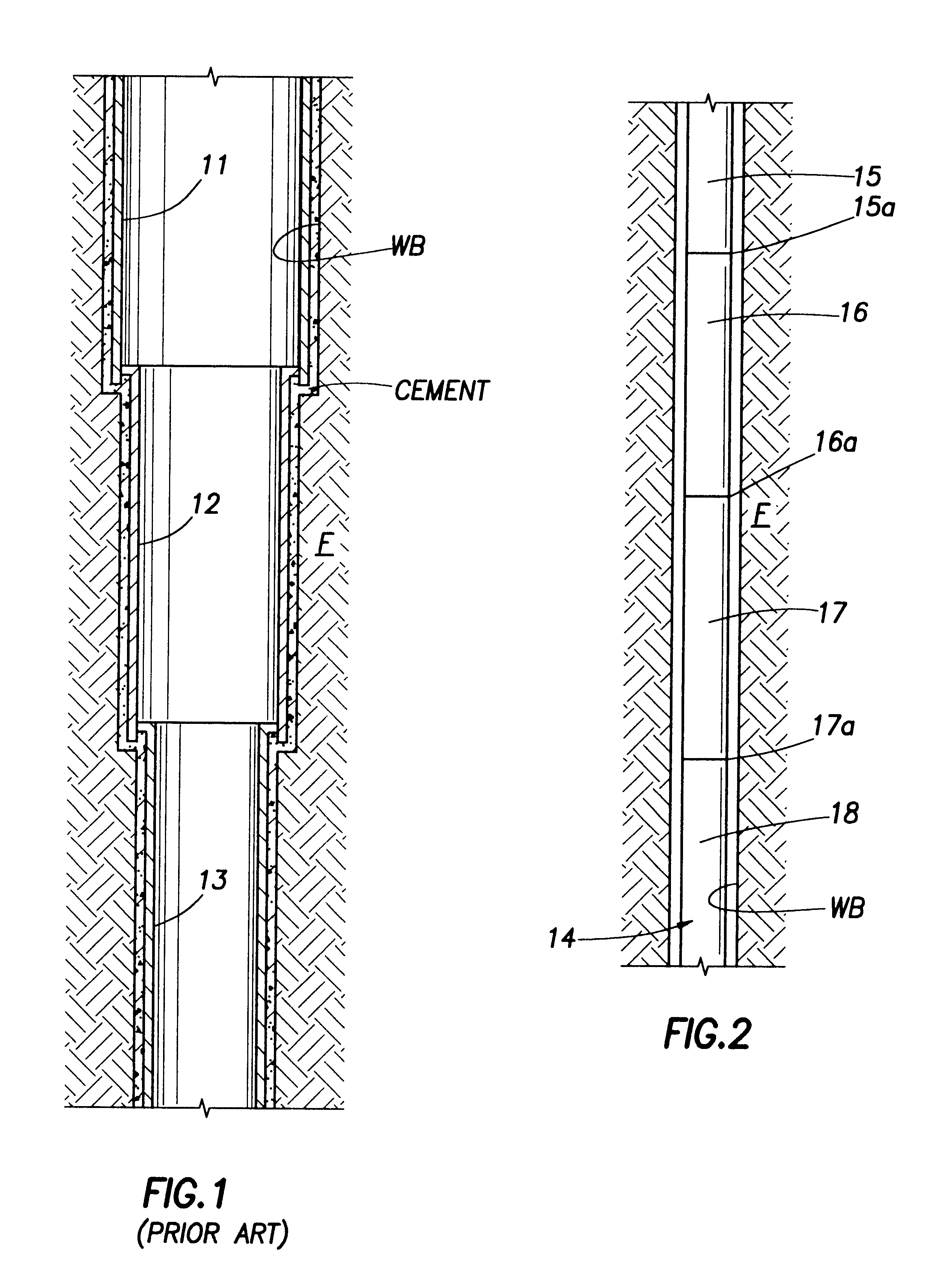
FIG. 1 indicates a conventional completion of a well bore WB drilled through a formation F in which successively set casing sections 11, 12, and 13 are cemented in deeper sections within the well bore. Since it is necessary to lower the casing section 12 through the casing section 11, the casing section 12 must be of a smaller external diameter than the internal diameter of the casing section 11. When drilling very deep wells, the described prior art process requires that the well have a relatively large initial well bore at the surface in order to have a suitably large well bore adjacent the subsurface producing formation.

FIG. 1 illustrates a conventional liner-type casing completion. In some wells, one or more of the strings 12 and 13 may extend all the way back to the surface rather than being suspended from the casing section immediately above. Some formation problems encountered in certain areas may prevent the typical casing program from being employed because of the risk of b...


PUM

PropertyMeasurementUnit
Fractionaaaaaaaaaa
Fractionaaaaaaaaaa
Fractionaaaaaaaaaa

Abstract

Methods and apparatus are provided for obtaining a secure mechanical connection and a pressure-tight seal in the overlapping area of two telescoping tubular bodies. The two bodies, including the overlapping area, are radially expanded to increase the inside diameter of the bodies. The expansion forces an annular seal in the overlapping area into a pressure-sealing engagement between the bodies. A string of pipe assembled from joints secured to each other by telescoping, threadedly engaged expanded pin and box connections may be radially expanded into a surrounding well bore to provide a cased well having an internal diameter greater than the original internal diameter of the pipe string. The seal in the connection comprises an annular elastomeric seal ring and an annular Teflon spacer ring carried in a specially dimensioned groove formed in either the box or the pin, or both members of the connection. Radial expansion of the connection causes axial contraction of the groove, which acts with the spacer ring to expand the seal ring radially to seal the annular space created between the expanded pin and box.

Description

1. Field of the InventionThe present invention relates generally to methods and apparatus for connecting tubular bodies. More specifically, the present invention relates to methods and apparatus for effecting a secure mechanical engagement and seal in the connected ends of pipe sections that are expanded radially to form an increased internal diameter pipe string.2. Description of the Prior ArtA new technique for casing well bores expands the well casing pipe radially after the casing pipe string has been lowered into a well bore. The casing string is enlarged radially by moving an oversized forging tool, or "pig," through the string, causing the string to expand radially beyond its original radial dimensions. This technique allows subsequent strings of casing to be lowered through the previously enlarged casing string sections and thereafter similarly expanded. The result is a well cased by a series of linked sections of casing having substantially the same internal diameters. The ...

Claims


Application Information

Patent Timeline
IPC IPC(8): E21B23/04E21B23/00E21B17/02E21B17/042E21B17/08E21B23/08E21B43/02E21B43/10F16L15/00F16L15/04F16L13/14F16J15/10F16L13/16
CPCE21B17/042E21B17/08E21B23/08E21B43/106F16L13/168F16L15/003E21B43/103Y10T29/4994
Inventor EVANS, M. EDWARDCOSTA, D. SCOTTBROCK, JAMES N.
Owner ENVENTURE GLOBAL TECH LLC
Why Eureka
Try Eureka