
Ink jet apparatus, ink jet apparatus driving method, and storage medium for storing ink jet apparatus control program

a technology of ink jet apparatus and control program, which is applied in the direction of printing, inking apparatus, other printing apparatus, etc., can solve the problems of deteriorating print quality

Inactive Publication Date: 2002-07-02
BROTHER KOGYO KK
View PDF8 Cites 17 Cited by
  • Summary
  • Abstract
  • Description
  • Claims
  • Application Information

AI Technical Summary

Benefits of technology

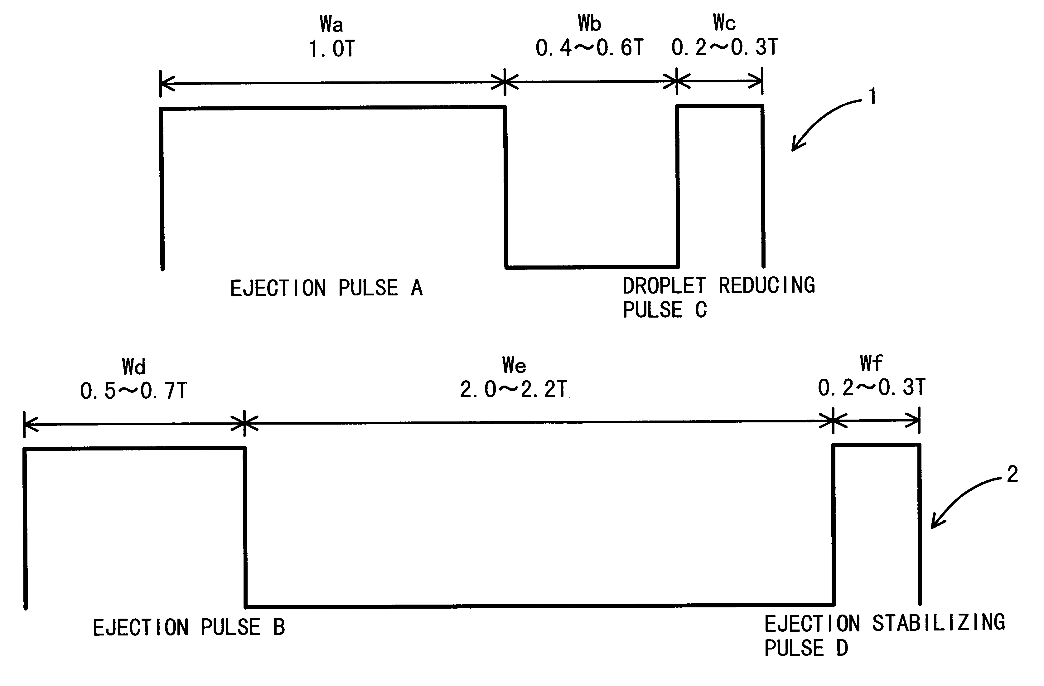
By setting the pulse widths and the pulse applying timing in this way, differences between the first and second drive waveforms in ink droplet ejection velocity and volume are minimized. In addition, ejection stability is ensured in each printing condition to which the first or second drive waveform is applied.

Problems solved by technology

However, in such a driving method, because pressure waves remaining in the ink channel are not suppressed, ejection of a minute ink droplet may become unstable or unwanted or no ink ejection may be caused when the ink jet head is driven at high printing frequencies and, as a result, print quality deteriorates.

Method used


Image

  • Ink jet apparatus, ink jet apparatus driving method, and storage medium for storing ink jet apparatus control program
  • Ink jet apparatus, ink jet apparatus driving method, and storage medium for storing ink jet apparatus control program
  • Ink jet apparatus, ink jet apparatus driving method, and storage medium for storing ink jet apparatus control program

Examples


Embodiment Construction

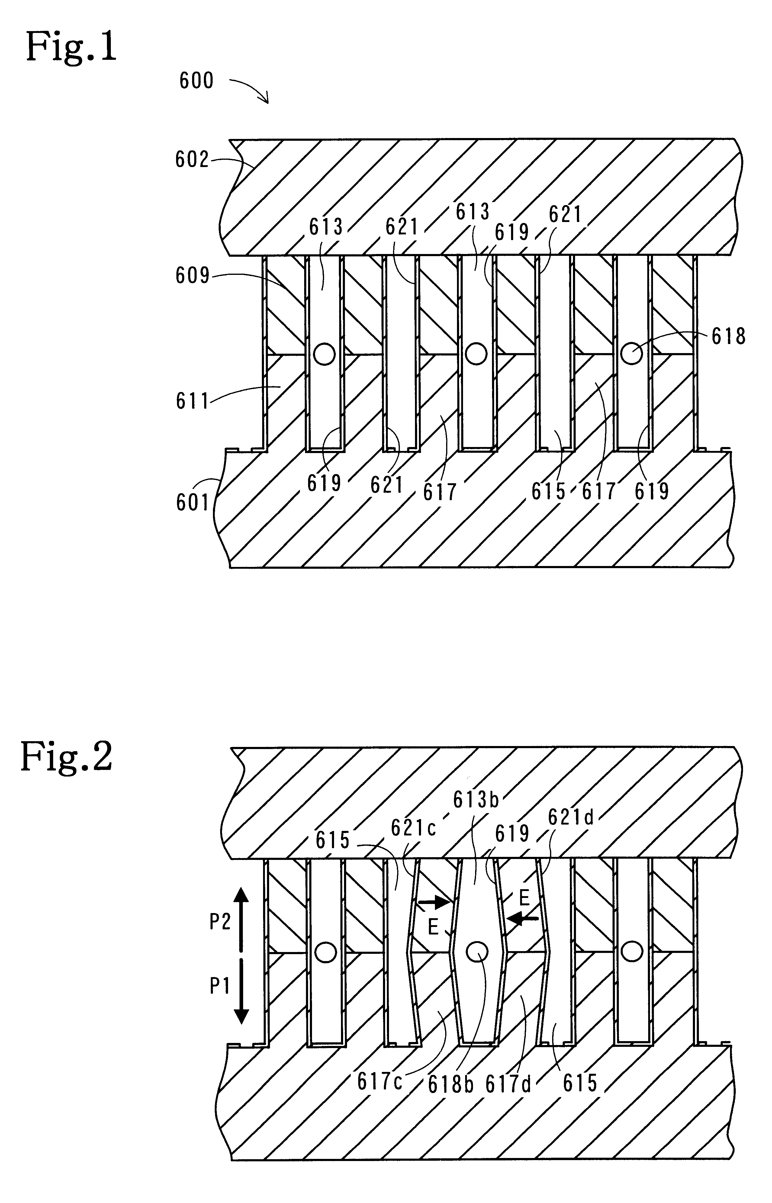
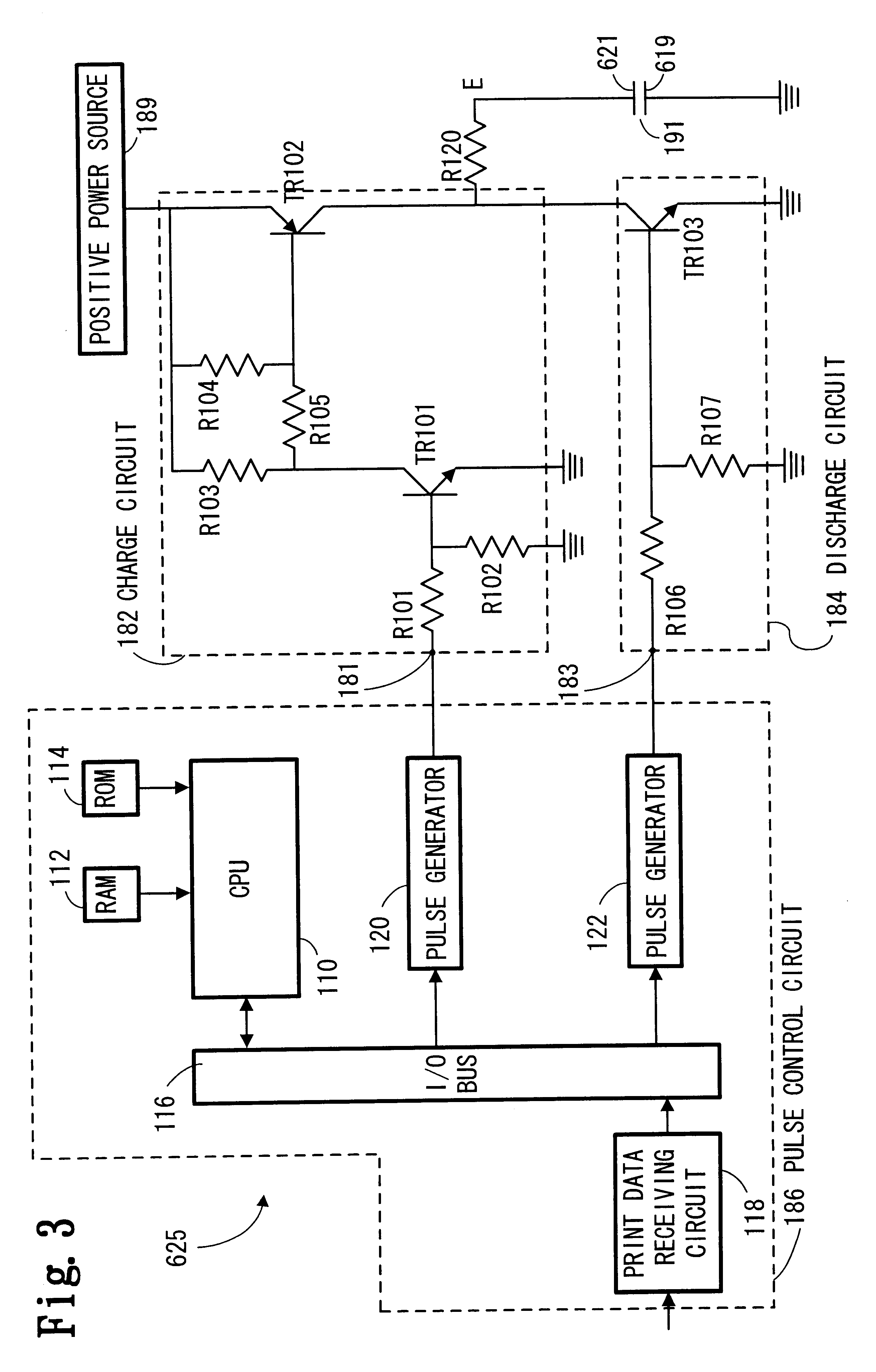
One embodiment of the invention will be described with reference to the attached drawings. Referring first to FIGS. 1 through 3, the basic structure of an ink jet apparatus according to one embodiment of the invention will be described.

As a drop-on-demand type ink jet apparatus, a shear mode type using piezoelectric ceramic is disclosed in U.S. Pat. Nos. 4,879,568, 4,887,100, 5,028,936, and 6,257,686, all of which are incorporated herein by reference. FIG. 1 shows a sectional view of an exemplary shear mode type jet apparatus. An ink jet head 600 includes an actuator substrate 601 and a cover plate 602. Formed in the actuator substrate 601 are a plurality of ink channels 613, each shaped like a narrow groove and extending perpendicularly to the sheet of FIG. 1, and a plurality of dummy channels 615 carrying no ink. The ink channels 613 and the dummy channels 615 are isolated by sidewalls 617. Each sidewall 617 is divided into upper and lower halves, that is, an upper wall 609 polari...


PUM


Abstract

When a dot is formed apart from other dots on a print medium, in response to a discontinuous print command, a first drive waveform is used. The first drive waveform includes an ejection pulse and an ink droplet reducing pulse for retrieving a portion of an ink droplet about to leave the nozzle. When a dot is formed to overlap other dots on a print medium, in response to one of continuous print commands, the second drive waveform is used. The second drive waveform includes an ejection pulse and an ejection stabilizing pulse for suppressing residual vibrations generated by the ejection pulse. By selectively using the first or the second drive waveform, an ink droplet smaller than 20 pl can be ejected stably even at high printing frequencies. As a result, high-quality, high-speed printing can be achieved.

Description

1. Field of InventionThe invention relates to an ink jet apparatus, an ink jet apparatus driving method, and a storage medium for storing an ink jet apparatus control program.2. Description of Related ArtIn conventional ink jet apparatuses, the volumetric capacity of an ink channel is changed by deformation of piezoelectric ceramic. When the volumetric capacity is reduced, ink in the ink channel is ejected as an ink droplet from a nozzle and, when the volumetric capacity is increased, ink flows into the ink channel from an ink guide port. In a printhead of this kind of ink jet apparatus, a plurality of ink channels are formed and separated by piezoelectric ceramic sidewalls. An ink supplying means, such as an ink cartridge, is connected to one end of each ink channel, and an ink ejection nozzle (hereinafter referred to as a nozzle) is provided for the other end of each ink channel. Selective reductions of the volumetric capacity of the ink channels by deformation of the sidewalls, a...

Claims


Application Information

Patent Timeline
Patent Type & Authority Patents(United States)
IPC IPC(8): B41J2/045
CPCB41J2/04508B41J2/04541B41J2/04551B41J2/04581B41J2/04588B41J2202/06B41J2202/10
Inventor TAKAHASHI, YOSHIKAZUITO, MASAHARU
Owner BROTHER KOGYO KK
Learn More