Liquid ejecting device and liquid ejecting method

a liquid ejecting device and liquid ejecting technology, which is applied in printing, inking apparatus, other printing apparatus, etc., can solve the problems of deteriorating printing quality, inability to eject ink perpendicular to the ejecting surface, and position shifting between, so as to achieve the effect of increasing the quality of printed images

Inactive Publication Date: 2005-08-25
SONY CORP
View PDF6 Cites 6 Cited by
  • Summary
  • Abstract
  • Description
  • Claims
  • Application Information

AI Technical Summary

Benefits of technology

[0032] Accordingly, it is an object of the present invention to perform stable ejection of liquid without shortening the life of means of producing bubbles, such as heating elements, and to control the flying characteristic of the liquid or a position to which the liquid is delivered. Specifically, the object is to control a direction in which liquid is ejected, for example, in a liquid ejecting device having heads each including a plurality of liquid ejecting portions arranged in parallel and a liquid ejecting method using heads each including a plurality of liquid ejecting portions arranged in parallel.

Problems solved by technology

However, various factors may cause a case in which an angle at which the ink is ejected is not perpendicular.
For example, when a nozzle sheet having the nozzles 1a formed thereon is bonded to the upper side of ink cells having heating elements, the problem is that positional shifting occurs between pairs of the ink cells and the heating elements, and the nozzles 1a.
However, if a shift occurs between the ink cells and the heating elements, and the nozzles 1a, the ink cannot be ejected perpendicularly to the ejection surface.
In addition, the line head 10 is only moved in the direction of the arrow in the plan view in FIG. 19B without being moved in the width direction of the printing paper P. This forms a white stripe B between the N-th printer-head chip 1 and the (N+1) printer-head chip 1, thus causing a problem of deterioration in printing quality.
This causes a discontinuous image and a stripe C which has a color thicker than the original color, thus causing a problem of deterioration in printing quality.
However, although Earlier Application 1 deflects the ink droplet by separately controlling the heating elements, the result of further study by the present Inventors has indicated that, when the method of Earlier Application 1 is employed, the ejection of the ink droplet may become unstable and a printed image having high quality cannot stably be obtained.
This situation causes a disadvantageous situation to size reduction in the heating element which is associated with increased resolution in the recent years.
As a result, damage to small-sized heating elements is enhanced.
This shortens the life of the heating elements, thus shortening the life of the head.
However, in the case of using provided heating elements which are small-sized in association with increased resolution in the recent years, when only some heating elements are driven to eject ink droplets, the supply to them of power enabling stable ejection causes a problem of a decrease in the life of the heating elements.
Conversely, in Earlier Application 4, when the amount of power supplied to each heating element is reduced, there is a possibility that the ink droplets cannot stably be ejected, as described above.

Method used


Image

  • Liquid ejecting device and liquid ejecting method
  • Liquid ejecting device and liquid ejecting method
  • Liquid ejecting device and liquid ejecting method

Examples


Embodiment Construction

[0081] An embodiment of the present invention is described below with reference to the accompanying drawings.

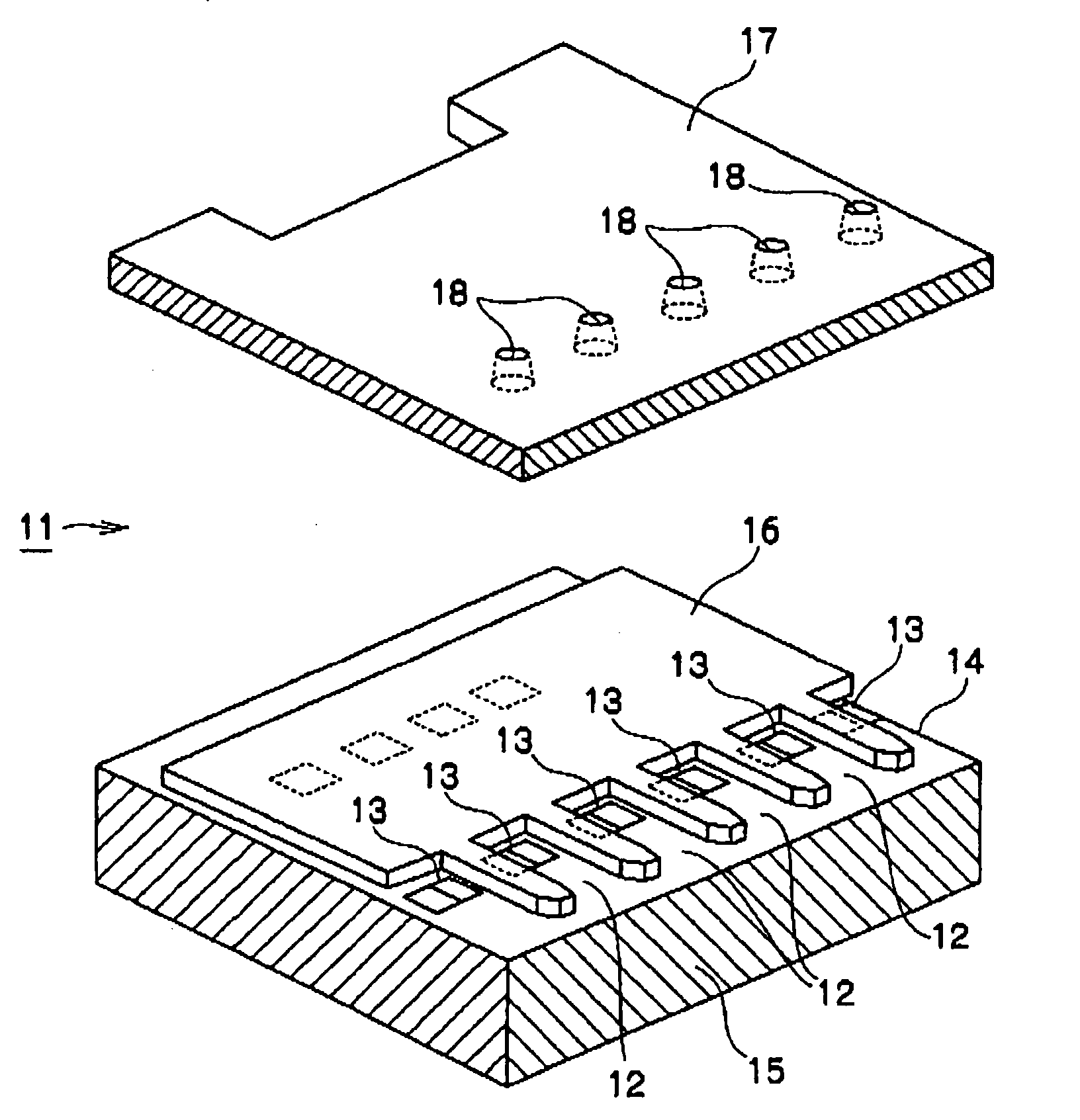
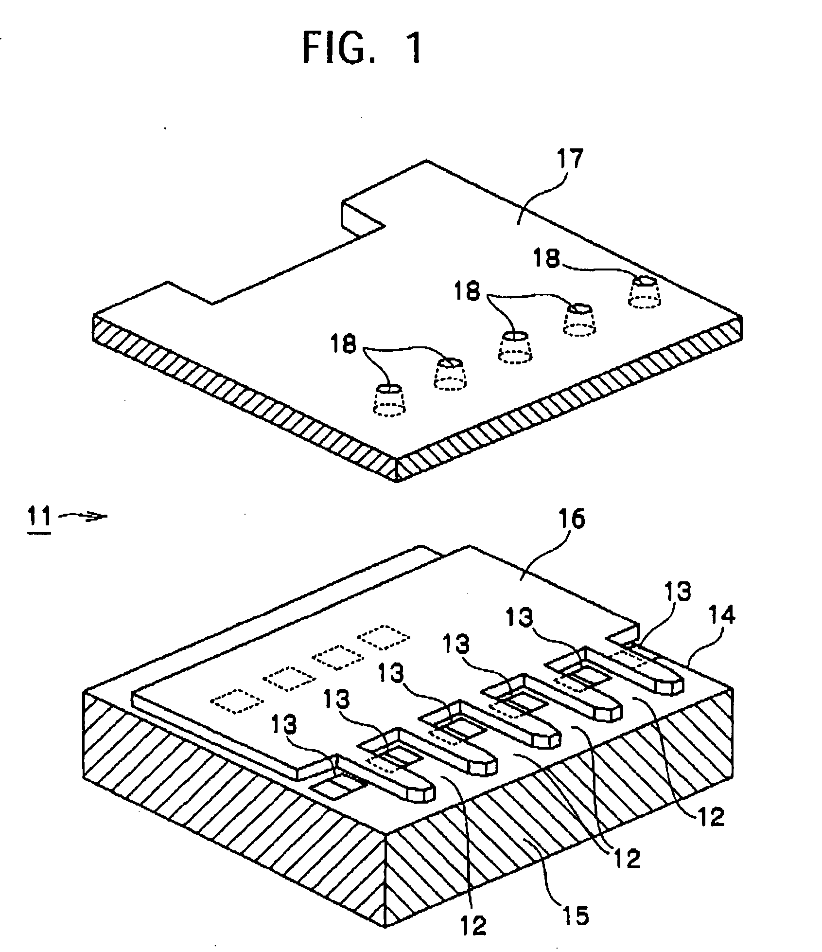
[0082]FIG. 1 is an exploded perspective view showing a printer-head chip 11 to which a liquid ejecting device of the present invention is applied. In FIG. 1, a nozzle sheet 17 is bonded to a barrier layer 16. The nozzle sheet 17 is shown, with it separated.

[0083] The printer-head chip 11 is of a type using the above thermal method. In the printer-head chip 11, a base member 14 includes a semiconductor substrate composed of silicon, etc., and heating resistors 13 (which correspond to bubble producing units or heating elements in the present invention, and which are used to produce bubbles in a liquid when being supplied with energy) formed on one surface of the semiconductor substrate 15. The heating resistors 13 are electrically connected to an external circuit by a conductor portion (not shown) formed on the semiconductor substrate 15.

[0084] The barrier layer 16 is made o...


PUM


Abstract

A liquid ejecting device and method control the flying characteristic of liquid while enabling stable ejection of the liquid, without shortening the life of bubble producing units (heating resistors). The liquid ejecting device has heads each including liquid ejecting portions arranged in parallel which each include a liquid cell, bisected heating resistors in the liquid cell which produce bubbles in liquid in the liquid cell in response to the supply of energy, and a nozzle for ejecting the liquid in the liquid cell by using the bubbles produced by the heating resistors. The heating resistors are supplied with energy, and a difference is set between a manner of supplying energy to one heating resistor and a manner of supplying energy to the other heating resistor. Based on the difference, a flying characteristic of the liquid ejected from the nozzle is controlled.

Description

BACKGROUND OF THE INVENTION [0001] 1. Field of the Invention [0002] The present invention relates to a technology for controlling flying characteristics of liquid or a position to which liquid is delivered and to liquid ejecting device and method in which liquid in liquid cell is ejected from a nozzle. The present invention specifically relates to, in liquid ejecting device including heads each having a plurality of liquid ejecting portions arranged in parallel and liquid ejecting method using the heads each having the ejecting portions arranged in parallel, a technology for controlling a direction (a direction in which liquid is delivered) in which liquid is ejected from each liquid ejecting portion. [0003] 2. Description of the Related Art [0004] Inkjet printers have been conventionally known as a type of liquid ejecting device including heads which each have a plurality of liquid ejecting portions arranged in parallel. A thermal method that uses thermal energy to eject ink is kno...

Claims


Application Information

Patent Timeline
Patent Type & Authority Applications(United States)
IPC IPC(8): B41J2/05B41J2/14
CPCB41J2/04505B41J2/04508B41J2/04526B41J2202/20B41J2/0458B41J2/14056B41J2/04533B41J2/35
Inventor EGUCHI, TAKEO
Owner SONY CORP
Why Eureka
Try Eureka