
Liquid ejecting apparatus

a liquid ejecting and apparatus technology, applied in the direction of printing, other printing apparatus, etc., can solve the problem of low surface tension of textile printing ink, and achieve the effect of reducing the thickness of liquid, and reducing the amount of liquid ejecting

Active Publication Date: 2015-09-10
SEIKO EPSON CORP
View PDF3 Cites 6 Cited by
  • Summary
  • Abstract
  • Description
  • Claims
  • Application Information

AI Technical Summary

Benefits of technology

The invention described in this patent is a system for ejecting liquids with constant ejection intervals, which results in stable ejection and reduced influence of residual vibration on the next ejection. This allows for stable formation of ejection droplets of various sizes, increasing the efficiency of the invention. Additionally, the invention includes a method for suppressing thickening of the liquid by micro-vibrating it at predetermined periods and reducing the impact of residual vibration on the next ejection.

Problems solved by technology

Due to this, the ink composition has characteristics which are suitable for textile printing; however, there is a tendency for the surface tension of the ink for textile printing to be low in comparison with aqueous inks which are typically used in the printers described above.

Method used


Image

  • Liquid ejecting apparatus
  • Liquid ejecting apparatus
  • Liquid ejecting apparatus

Examples


Embodiment Construction

[0033]Below, embodiments for realizing the invention will be described with reference to the attached diagrams. Here, in the embodiments which are described below, various types of limitations are applied as favorable specific examples of the invention; however, the range of the invention is not limited to these aspects unless it is particularly stated in the description below that the invention is limited. In addition, an ink jet type recording apparatus (below, a printer) will be described below as an example of a liquid ejecting apparatus of the invention.

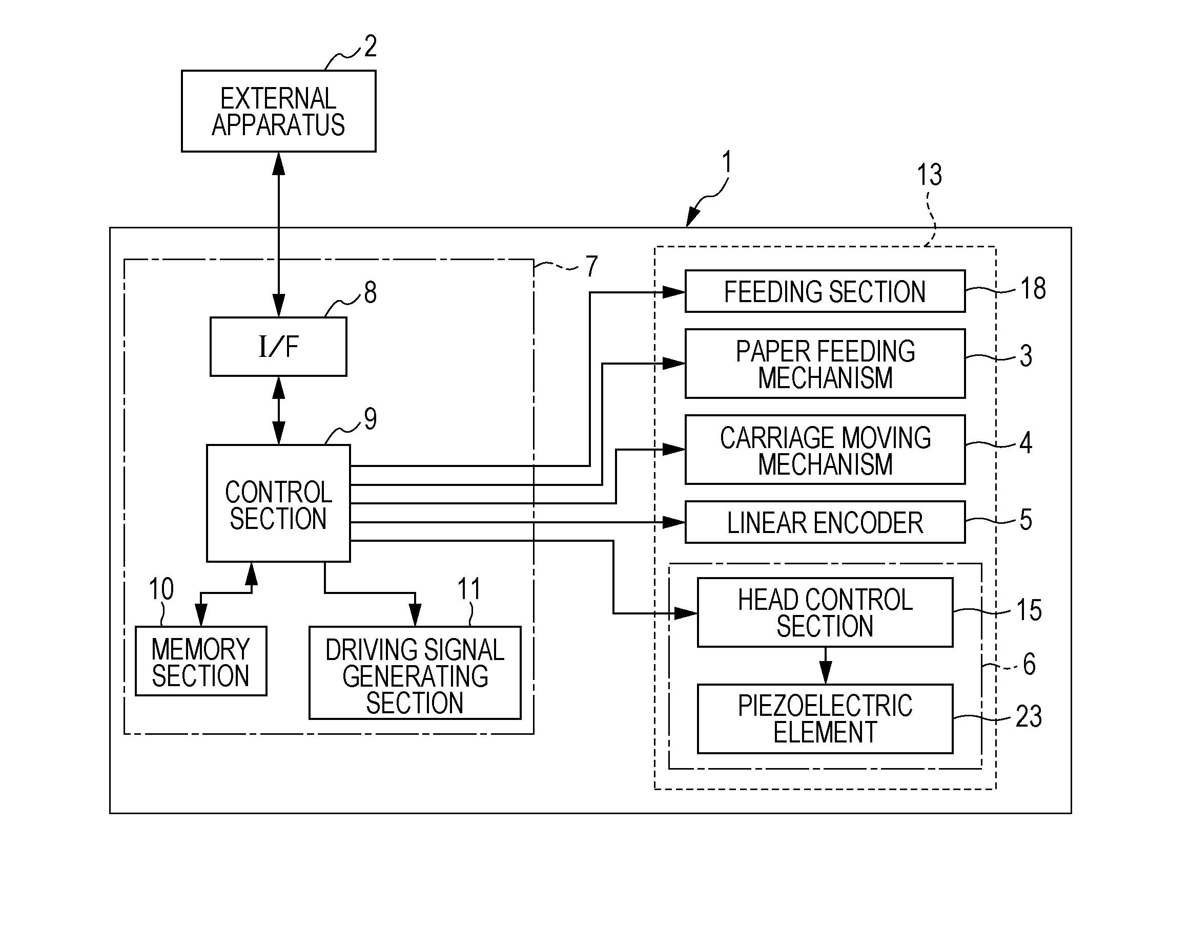
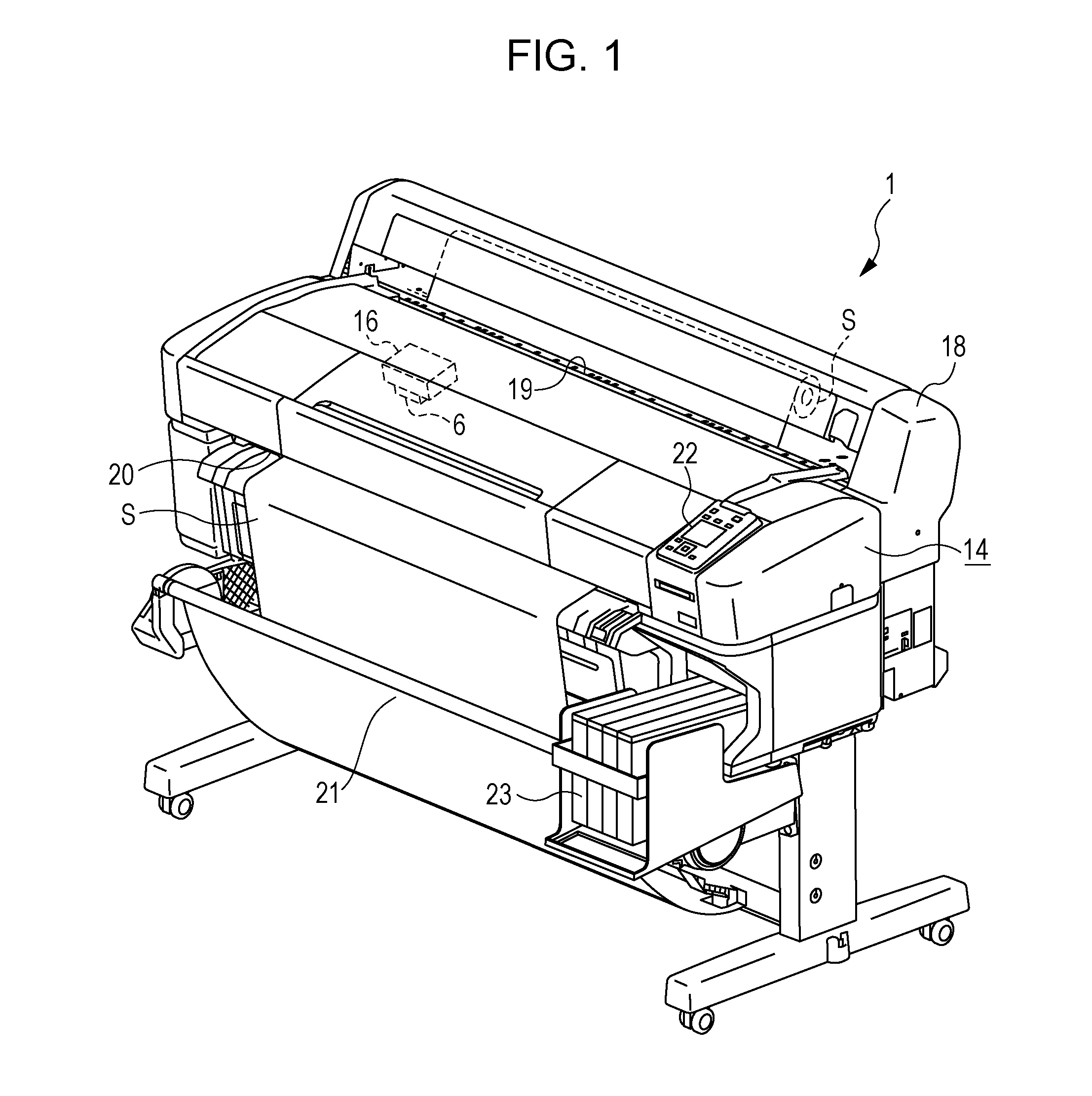
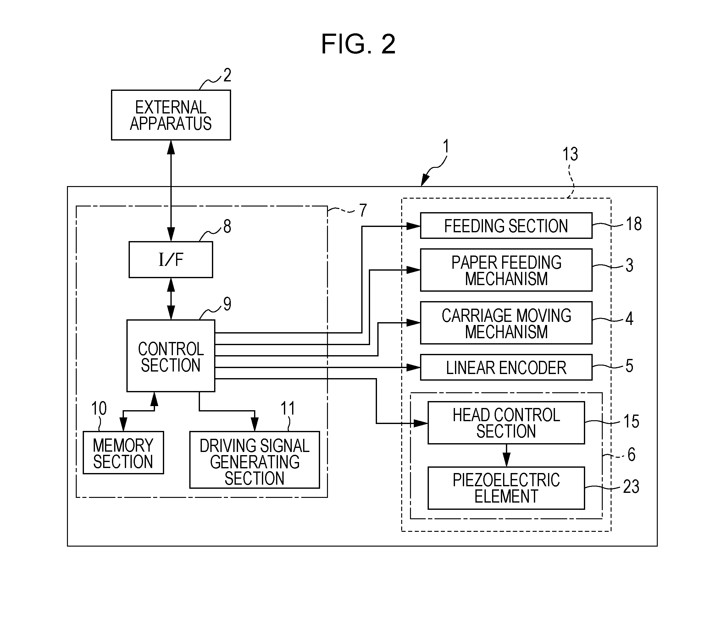
[0034]FIG. 1 is a perspective diagram which illustrates a configuration of a printer 1 and FIG. 2 is a block diagram which illustrates an electrical configuration of the printer 1. An external apparatus 2 is an electronic apparatus such as, for example, a computer, a digital camera, or a cell phone. The external apparatus 2 is electrically connected with the printer 1 wirelessly or by a cable and transmits printing data accordin...


PUM


Abstract

[Object] To provide a liquid ejecting apparatus which is able to eject a liquid where the surface tension is comparatively low in a stable manner.[Solution] In relation to a driving signal for ejecting ink for textile printing where the surface tension is 22 [mN] or more and 30 [mN] or less from a nozzle, the interval between the first ejection driving pulse DP1 and the second ejection driving pulse DP2 and the interval between the second ejection driving pulse DP2 of a cycle T(n) and the first ejection driving pulse DP1 of a cycle T(n+1) are set to be Δt1. Due to this, in a case where medium dots are continuously formed over a plurality of continuous cycles, the ejecting intervals of the ink are set to be constant.

Description

CROSS-REFERENCE TO RELATED APPLICATIONS[0001]This application claims the benefit of U.S. Provisional application 61 / 949,132 filed Mar. 6, 2014, titled “LIQUID EJECTING APPARATUS”, which is incorporated herein by reference in its entirety.TECHNICAL FIELD[0002]The invention relates to a liquid ejecting apparatus such as an ink jet recording apparatus, in particular, to a liquid ejecting apparatus which handles a liquid where the surface tension is comparatively low.BACKGROUND ART[0003]The liquid ejecting apparatus is provided with a liquid ejecting head and is an apparatus which ejects (discharges) various types of liquid from the liquid ejecting head. Examples of the liquid ejecting apparatus include image recording apparatuses such as an ink jet printer (referred to below simply as a printer) or an ink jet plotter; however, recently, the invention has been applied to various types of manufacturing apparatuses which take advantage of the feature that it is possible to accurately land...

Claims


Application Information

Patent Timeline
IPC IPC(8): B41J2/045B41J2/14
CPCB41J2/1433B41J2/04588B41J2/04581
Inventor TSUBOTA, SHINICHI
Owner SEIKO EPSON CORP
Learn More