Gas range
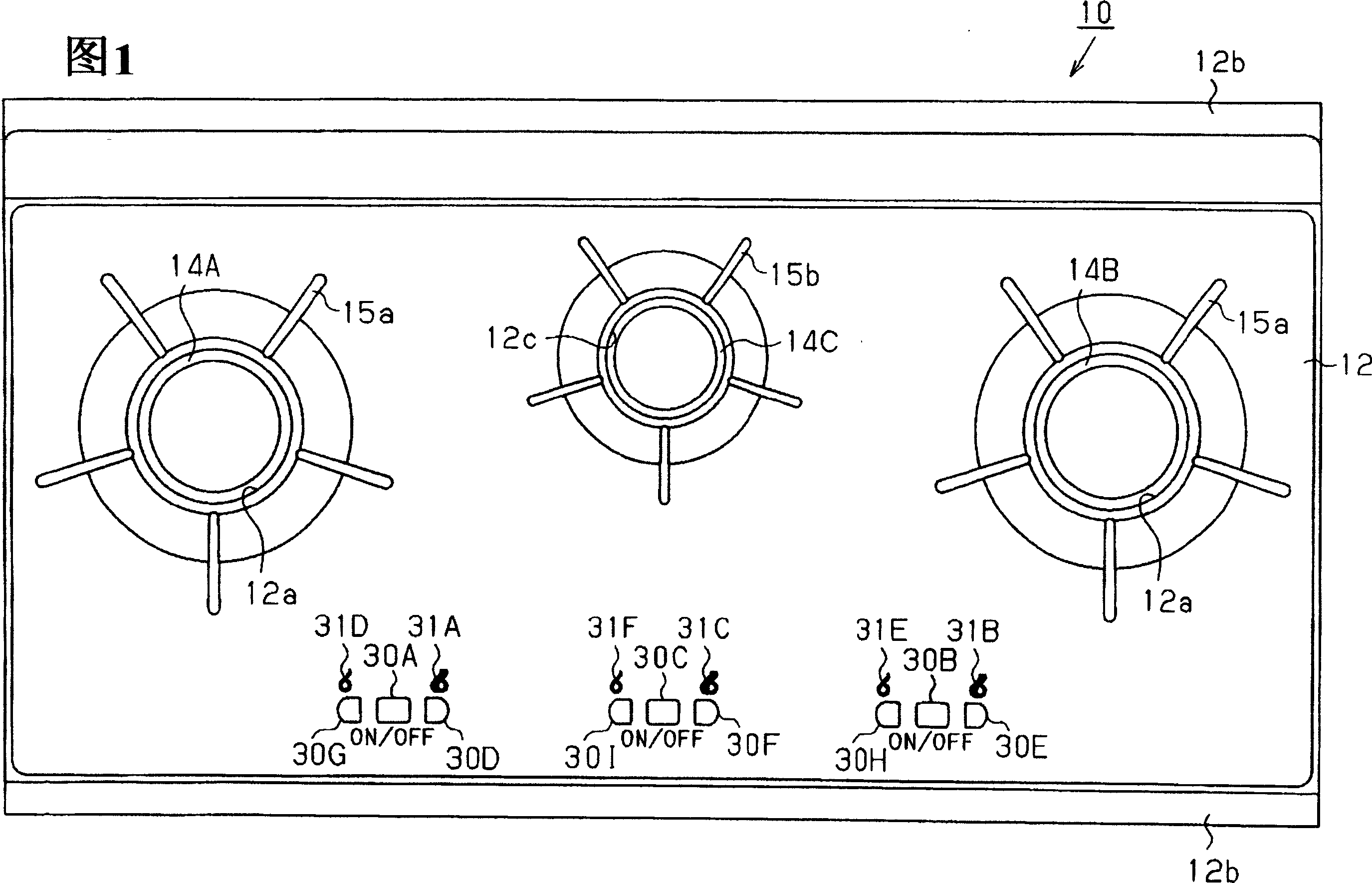
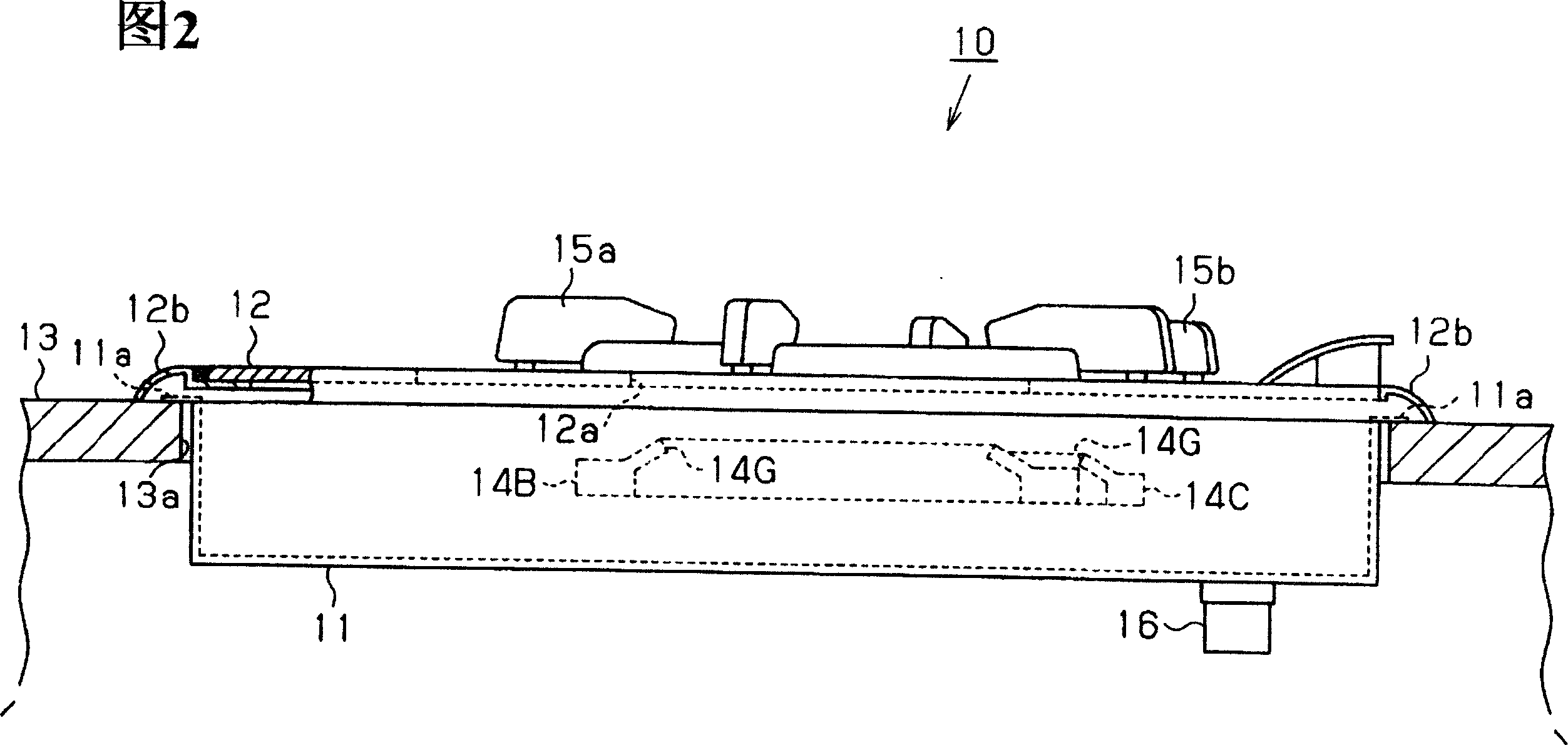
A technology of gas stoves and gas, applied in the field of gas stoves, can solve the problems of difficult bending processing and increased production costs, and achieve the effect of miniaturization of the overall shape and suppression of thickening
- Summary
- Abstract
- Description
- Claims
- Application Information
AI Technical Summary
Problems solved by technology
Method used
Image
Examples
no. 2 Embodiment approach
[0046] Next, a second embodiment of a gas range embodying the present invention will be described with reference to FIG. 7 . In the second embodiment, the arrangement positions of the components of the first embodiment are changed. In the following description, the same reference numerals are used for the same parts as those of the first embodiment, and detailed description thereof will be omitted.
[0047] As shown in FIG. 7 , in the main body case 11 , a large burner 14A on one side is arranged in the left front corner of the main body case, and its gas inlet 14AD faces right rearward. The large burner 14B on the other side is arranged on the right side of the center of the main body case 11, and its gas inlet 14BD faces the large burner 14A. The small burner 14C is arranged at the right rear corner of the main body case 11, that is, on the rear position of the large burner A, and its gas mixing pipe 14CK extends parallel to the rear side of the main body case 11, and the g...
no. 3 Embodiment approach
[0054] The following is based on Figure 8 The third embodiment of the gas range which embodied the present invention will be described. In the third embodiment, the arrangement positions of the components of the first embodiment are changed.
[0055] like Figure 8 As shown, in the main body case 11, a large burner 14A on one side is arranged at the right front corner of the main body case 11, and its gas inlet 14AD faces the rear side. The large burner 14B on the other side is arranged at a position slightly to the front right of the center of the main body case 11, and its gas inlet 14BD faces the large burner 14A. The small burner 14C is arranged in the large right rear corner of the main body box, that is, the oblique rear of the large burner 14B. The gas introduction port 14CD of the small burner 14C faces leftward, that is, faces the gas volume regulating valve 19C. The center of the small burner 14C is located further back than the connecting line between the cente...
PUM
 Abstract
Description
Claims
Application Information
 - R&D
- Intellectual Property
- Life Sciences
- Materials
- Tech Scout
- Unparalleled Data Quality
- Higher Quality Content
- 60% Fewer Hallucinations
Browse by: Latest US Patents, China's latest patents, Technical Efficacy Thesaurus, Application Domain, Technology Topic, Popular Technical Reports.
© 2025 PatSnap. All rights reserved.Legal|Privacy policy|Modern Slavery Act Transparency Statement|Sitemap|About US| Contact US: help@patsnap.com


