Liquid droplet jetting apparatus

a technology of liquid droplets and jetting apparatuses, which is applied in the field of liquid droplet jetting apparatuses, can solve the problems of increasing the cost, increasing the viscosity, and increasing the thickness of ink, so as to reduce the cost of tubes, suppress the thickening of liquid, and shorten the total length of tubes.

Active Publication Date: 2009-06-04
BROTHER KOGYO KK
View PDF29 Cites 4 Cited by
  • Summary
  • Abstract
  • Description
  • Claims
  • Application Information

AI Technical Summary

Benefits of technology

[0038]According to the present invention, since the liquid tank and the two heads are connected in series, it is possible to shorten the total length of the tube as compared to a case in which the liquid tank and each of the two heads are connected by two tubes (connected in parallel). Therefore, it is possible to reduce the cost of the tubes, and moreover it is possible to suppress the thickening of the liquid in the tubes and the entry of an air bubble into the tubes.
[0039]In addition to this, in the second head in which the nozzle is positioned at a position higher than in the first head, when the meniscus in the nozzle is broken, since it is possible to let the liquid which has flowed reversely from the second head, escape to the liquid tank, no substantial pressure is exerted on the liquid in the first nozzle of the first head, and the breaking of the meniscus in the first nozzle is prevented.

Problems solved by technology

Incidentally, in case of connecting individually (connecting in parallel) one ink cartridge and the plurality of ink-jet heads by the plurality of tubes, the total tube length becomes long, and it leads to an increase in the cost.
Moreover, when the tube is made of a resin (material) and has some air permeability, there is a problem of gradual drying of the ink, which leads to an increase in a viscosity (thickening of ink).
Or, there is a problem of entry of an air bubble into the tube from outside.
Therefore, when such ink including the thickened ink and air bubbles is supplied to the ink-jet head, there is a possibility of occurrence of a jetting defect in the nozzle.
In such case, when these two ink-jet heads are connected in series (connected serially), there is a possibility that the following problem arises.
Therefore, there is a rise in the pressure of the ink inside the ink-jet head having the liquid droplet jetting surface at a lower position, and the meniscus inside the nozzle breaks.
As a result, a large amount of ink might leak out from both the ink-jet heads.

Method used


Image

  • Liquid droplet jetting apparatus
  • Liquid droplet jetting apparatus
  • Liquid droplet jetting apparatus

Examples


first modified embodiment

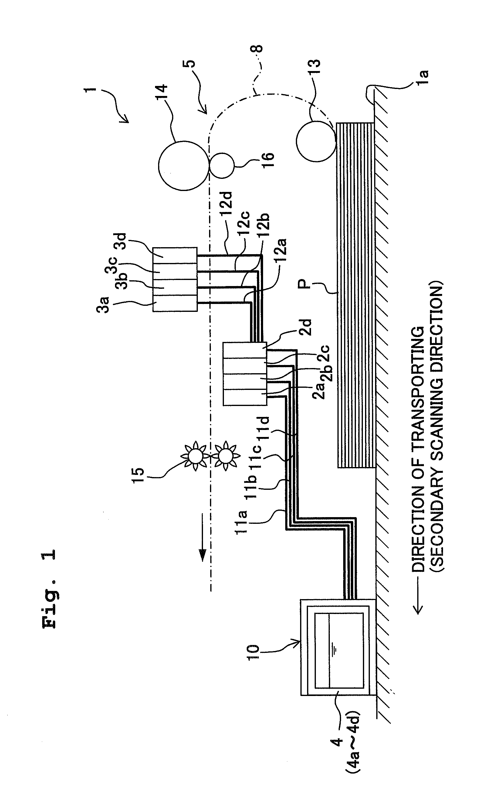
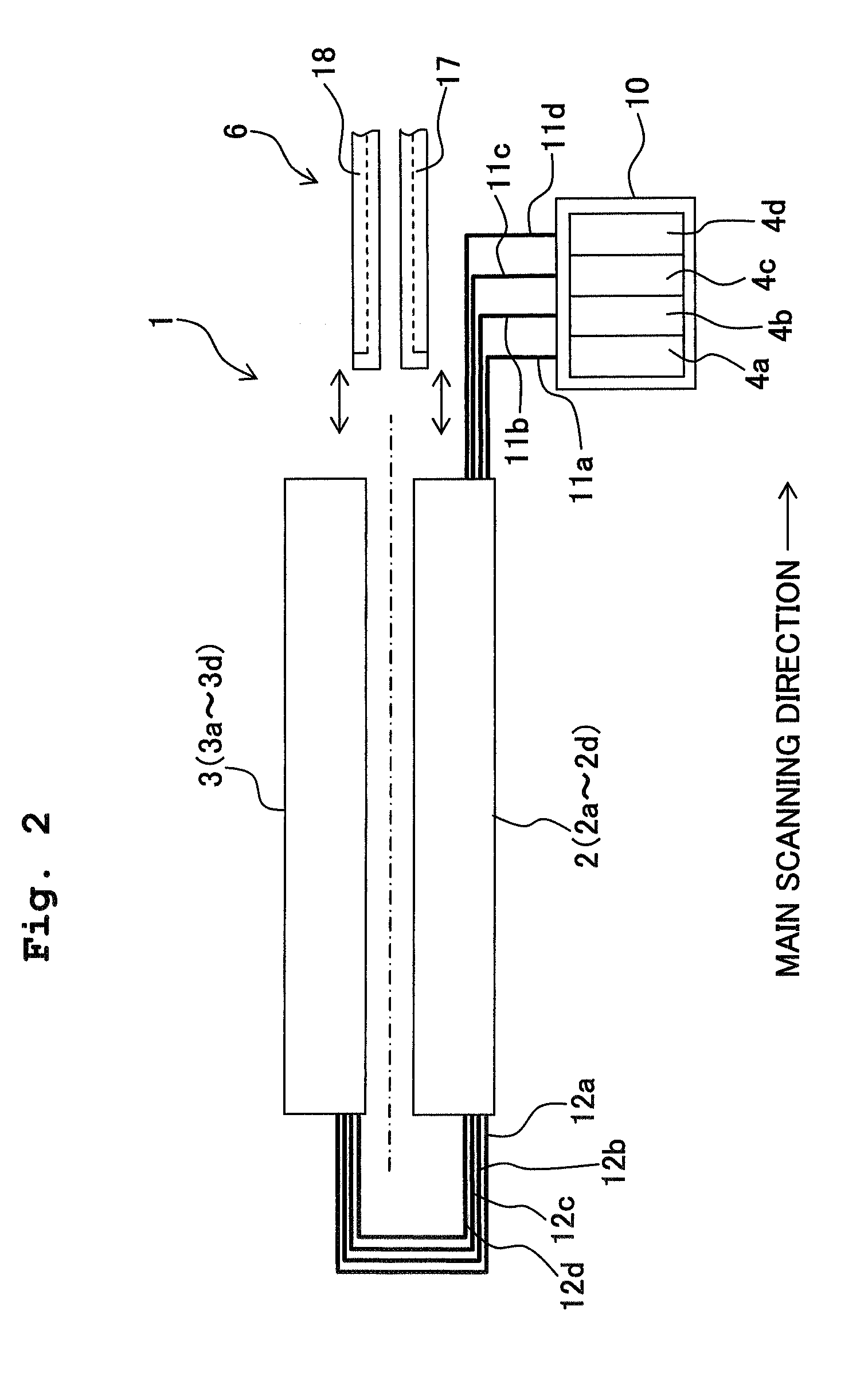
[0099]In the embodiment, the ink cartridge 4 which is detachably mounted on the holder 10 and the first head 2 are connected by the tube 11 (refer to FIG. 1). However, as in a printer 1A shown in FIG. 13, four sub tanks 91 (buffer tanks) may be arranged, between the first head 2 and the ink cartridge 4 which is detachable, at a position lower than the upper surface of the first head 2 (liquid droplet jetting surface on which the first nozzles 55a are arranged). Each of the sub tanks 91 is connected to one of the ink cartridges 4 by the tube 11, and is connected to the first head 2 by the tube 11. In other words, the sub tanks 91 supply the ink to the first head 2 upon storing once the ink supplied from the ink cartridge 4. In this case, the sub tank 91 corresponds to a part of a liquid storage container of the present invention which stores the ink to be supplied to the first head 2 and the second head 3. In this case, since the sub tank 91 is provided between the ink cartridge (mai...

second modified embodiment

[0102]The printer 1 of the embodiment includes the first head 2 and the second head 3 arranged on both sides sandwiching the paper transporting path 8, such that it is possible to print simultaneously on both surfaces of the printing paper P. However, the present invention is also applicable to a printer for single face printing (single-sided printing). In that case, it is possible to perform a high-speed printing by using two heads.

[0103]In other words, as shown in FIG. 14, in a printer 1B of a second modified embodiment, the paper transporting path 8 of the printing paper P which is transported by the main roller 14 and the spur roller 15, is inclined to be directed downwardly toward a downstream side of the transporting direction. The first head 2 and the second head 3 are arranged, in this order from a lower side, at an upper side of the inclined paper transporting path 8. In the printer 1B, a lower surface of the first head 2 and a lower surface of the second head 3 are liquid ...


PUM


Abstract

A printer includes a first head in which first nozzles are formed, a second head in which second nozzles located at a higher position than the first nozzle are formed, and an ink cartridge positioned at a lower position than the first and second nozzles. Moreover, the first head is connected to the ink cartridge via a tube, and the second head is connected to the first head via a tube. Accordingly, the second head is connected to the ink cartridge via the first head. It is possible to shorten the tubes by connecting serially the ink cartridge and the two heads, and to prevent from breaking simultaneously a meniscus in the nozzles of both the heads located at different height positions.

Description

CROSS REFERENCE TO RELATED APPLICATION[0001]The present application claims priority from Japanese Patent Application No. 2007-309964, filed on Nov. 30, 2007, the disclosure of which is incorporated herein by reference in its entirety.BACKGROUND OF THE INVENTION[0002]1. Field of the Invention[0003]The present invention relates to a liquid droplet jetting apparatus which includes two liquid droplets jetting heads each having a plurality of nozzles through which the liquid droplets are jetted, a height-position of the nozzles in one head being different from that in the other head.[0004]2. Description of the Related Art[0005]An ink-jet printer which records an image and characters on a recording medium such as a printing paper, generally includes an ink-jet head (liquid droplets jetting head) having nozzles through which liquid droplets of an ink is jetted, and an ink cartridge (liquid tank, liquid storage container) which stores the ink to be used in the ink-jet head. The ink-jet head...

Claims


Application Information

Patent Timeline
Patent Type & Authority Applications(United States)
IPC IPC(8): B41J2/175B41J2/165
CPCB41J2/17509B41J3/60B41J3/543
Inventor KUBO, TOMOYUKIUMEDA, TAKAICHIROKATO, RYUJISAKURAI, HISAKI
Owner BROTHER KOGYO KK
Why Eureka
Try Eureka