Fluid ejecting apparatus

a technology of ejecting apparatus and fluid, which is applied in the direction of printing and inking apparatus, etc., can solve the problems of clogging of the nozzle, humidification of the printing paper surface, and particularly serious problems, and achieve the effect of suppressing the thickening of fluid and reducing flushing

Active Publication Date: 2011-07-14
SEIKO EPSON CORP
View PDF1 Cites 1 Cited by
  • Summary
  • Abstract
  • Description
  • Claims
  • Application Information

AI Technical Summary

Benefits of technology

[0007]An advantage of some aspects of the invention is to provide a fluid ejecting apparatus capable of reducing flushing by evaporating a solvent in a narrow space in order to suppress thickening of a fluid at nozzle openings.

Problems solved by technology

In such printers, there has been a problem in that thickening of the ink caused by the ink evaporating from the nozzles of a recording head has led to the occurrence of nozzle clogging.
This issue is particularly serious in printers that have large capacities, such as line-head printers, large-size printers, and so on.
Furthermore, humidifying the interior of the housing also results in the humidification of the printing paper surface, paper that is standing by for printing, and so on, and because the humidity within the paper has risen as a result, there has been a problem in that ink that has been ejected during printing does not dry easily.
Meanwhile, carrying out the aforementioned flushing operations wastes time.
Furthermore, the operations for carrying out the flushing (movement to a flushing position) are necessary, and also waste ink.

Method used


Image

  • Fluid ejecting apparatus
  • Fluid ejecting apparatus
  • Fluid ejecting apparatus

Examples


first embodiment

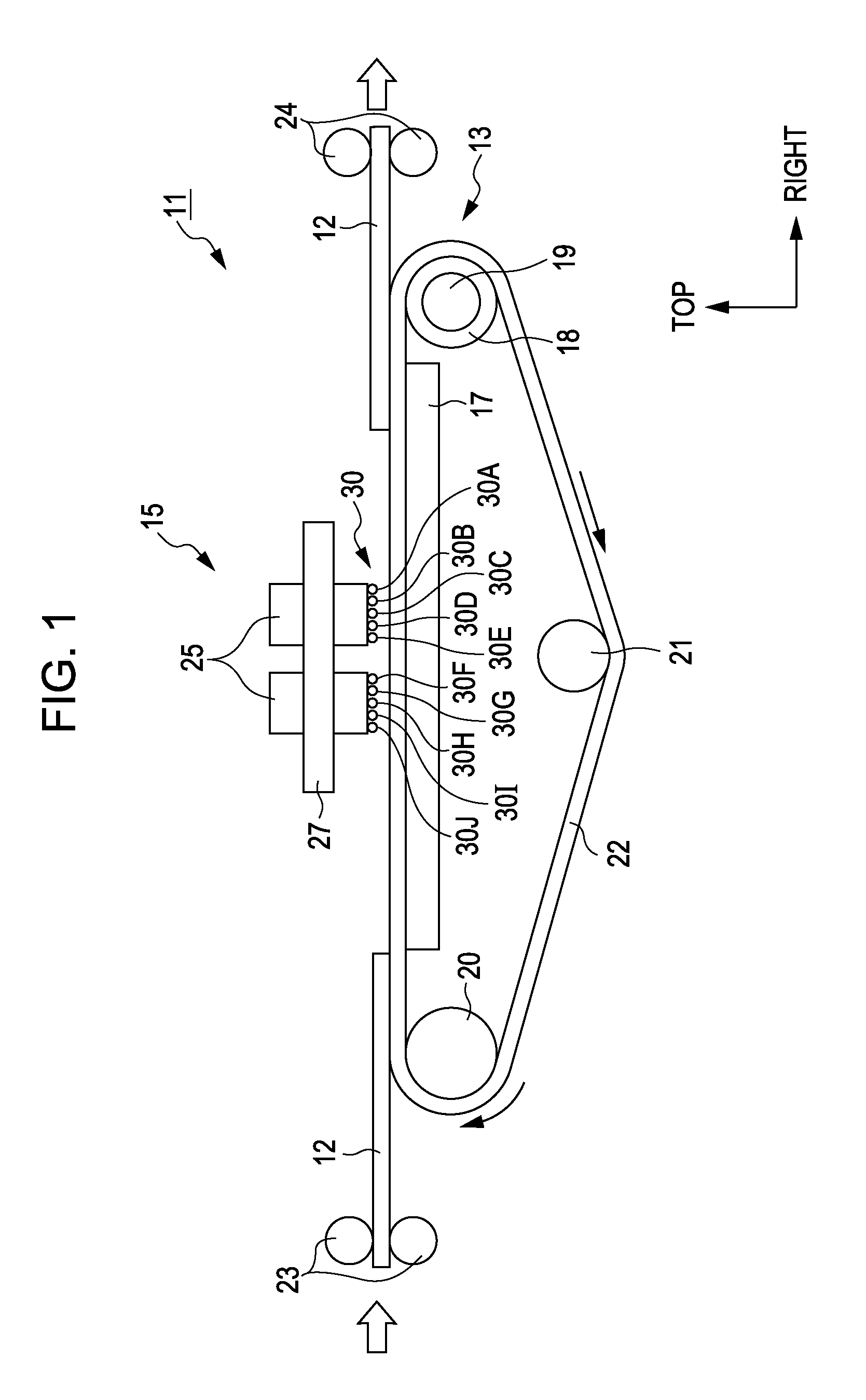
[0038]Hereinafter, a specific embodiment of an ink jet printer (called simply a “printer” hereinafter), serving as an example of a fluid ejecting apparatus according to the invention, will be described based on the drawings. In particular, this embodiment illustrates a line-head printer having a recording head unit anchored across the entirety of the width direction of paper.

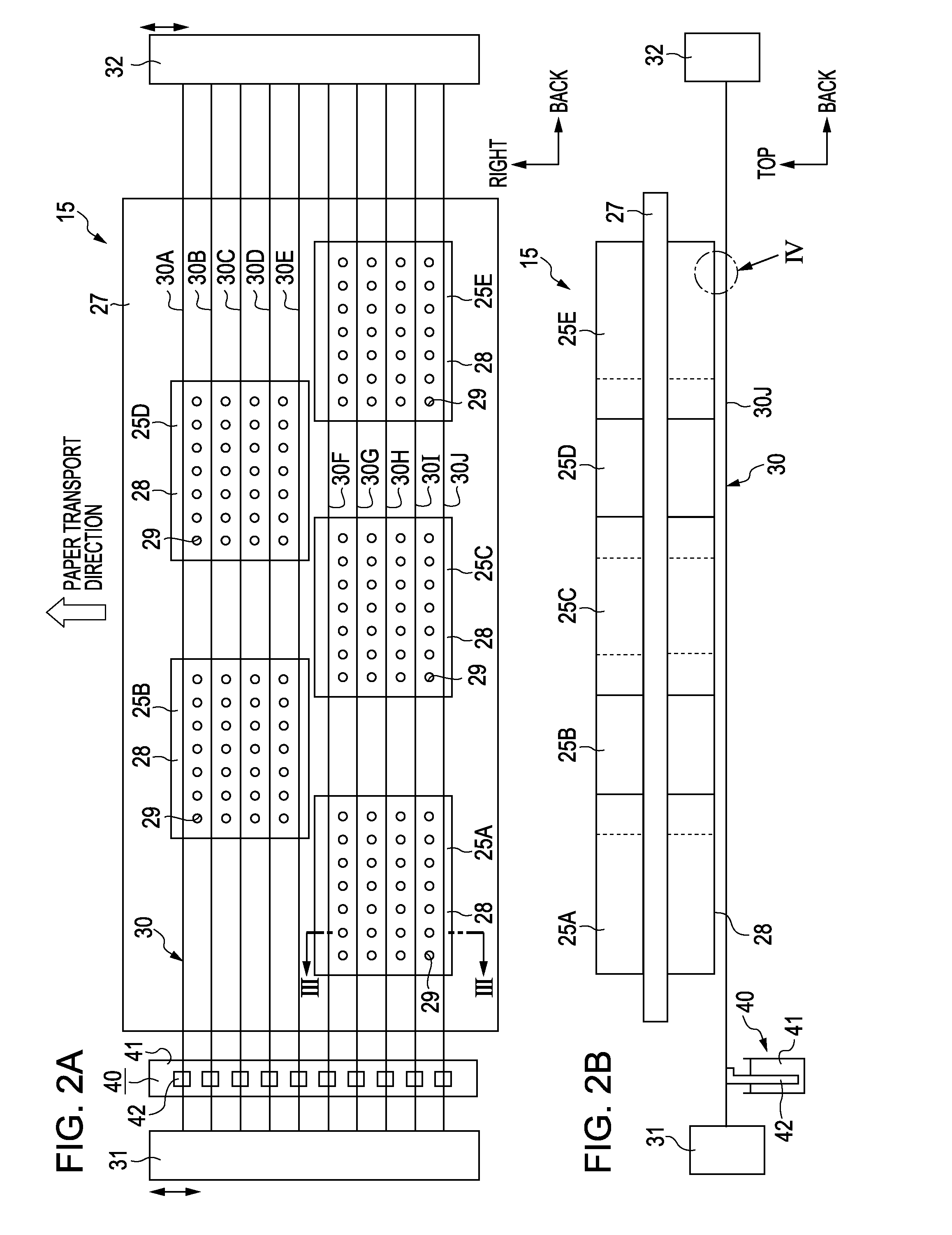
[0039]Note that the terms “depth direction”, “horizontal direction”, and “vertical direction” as used in the descriptions hereinafter refer respectively to the depth direction, horizontal direction, and vertical direction indicated by the arrows in FIG. 1 and FIG. 2.

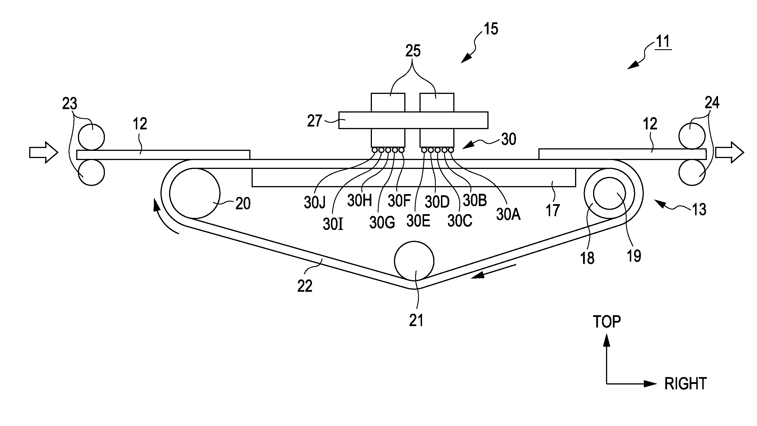
[0040]As illustrated in FIG. 1, an ink jet printer 11 serving as a recording apparatus includes a transport unit 13 for transporting paper 12 that serves as a target, and a recording head unit 15. The recording head unit 15 is provided above the transport unit 13.

[0041]The transport unit 13 includes a platen 17, which has a long rectangular shape in ...

second embodiment

[0074]Next, a second embodiment will be described using FIGS. 7A and 7B. Note that the second embodiment differs from the first embodiment only in that the configuration of the solvent supply unit has been changed; because the other configurations are common between the two embodiments, identical constituent elements will be assigned the same reference numerals and detailed descriptions thereof will be omitted.

[0075]As shown in FIGS. 7A and 7B, in addition to unit heads 25 for line-printing, heads 54, 55, 56, and 57, serving as solvent supply units that eject water, are disposed on both sides of the unit heads 25 for printing. Furthermore, the twisted strings 30 (30A to 30J) are wound upon rollers 50 and 51. The rollers 50 and 51 are rotationally driven by motors 52 and 53. Furthermore, a humidity sensor 58 is provided for the twisted strings 30, the humidity sensor 58 making contact with the twisted strings 30 and detecting the moisture level thereof. Note that the moisture level c...

third embodiment

[0078]Next, a third embodiment will be described using FIGS. 8 through 11. Note that the third embodiment differs from the first embodiment only in that the configurations of the solvent holding member and the solvent supply unit have been changed; because the other configurations are common between the two embodiments, identical constituent elements will be assigned the same reference numerals and detailed descriptions thereof will be omitted.

[0079]As shown in FIGS. 8, 9A and 9B, two porous plates 60 (60A and 60B) serving as solvent holding members are disposed on the bottom surface of the unit heads 25. The porous plates 60 are supported by a first mobile support member 63 disposed on the front side of the plate 27 and a second mobile support member 64 disposed on the rear side of the plate 27. The first mobile support member 63 and the second mobile support member 64 are capable of moving in the transport direction of the paper 12, and thus the porous plates 60 (60A and 60B) can ...


PUM


Abstract

A fluid ejecting apparatus, having a fluid ejecting head having a nozzle that ejects a fluid containing a solvent toward a target, includes a solvent holding member, disposed in a position that is opposite to a nozzle formation surface in which the nozzle of the fluid ejecting head is formed between the nozzle formation surface and the target but that is not opposite to the nozzle, that holds the solvent contained in the fluid.

Description

BACKGROUND[0001]1. Technical Field[0002]The present invention relates to fluid ejecting apparatuses such as ink jet printers or the like.[0003]2. Related Art[0004]Ink jet printers (called simply “printers” hereinafter) have been widely known for some time as fluid ejecting apparatuses that eject ink onto recording paper (a target). In such printers, there has been a problem in that thickening of the ink caused by the ink evaporating from the nozzles of a recording head has led to the occurrence of nozzle clogging. Accordingly, the printers normally carry out a flushing operation that forcefully ejects the ink within the nozzles, an operation that is separate from the ejecting of ink onto the recording paper. Furthermore, JP-A-2009-6682 discloses a liquid ejecting apparatus in which the liquid within the nozzles is resistant to thickening. In order to realize a fluid ejecting apparatus in which the liquid within the nozzles is resistant to thickening even without covering the nozzles...

Claims


Application Information

Patent Timeline
Patent Type & Authority Applications(United States)
IPC IPC(8): B41J2/015
CPCB41J2/155B41J2202/20B41J2/16552B41J2/165
Inventor MIYAZAWA, HISASHI
Owner SEIKO EPSON CORP
Why Eureka
Try Eureka