
Small-caliber combined rib bottom pile rapid protection technology for super-large high-position mud-rock flow

A small diameter, debris flow technology, applied in sheet pile walls, excavation, construction, etc., can solve the problems of high time cost, unfavorable emergency treatment of debris flow, etc., and achieve the effect of preventing debris flow, clear treatment procedures, and reducing possibility.

Active Publication Date: 2015-01-28
中国地质环境监测院
View PDF5 Cites 1 Cited by
  • Summary
  • Abstract
  • Description
  • Claims
  • Application Information

AI Technical Summary

Problems solved by technology

[0004] However, it should be noted that the cast-in-place reinforced concrete bed sill needs to be excavated, and the time cost is high, especially in the rainy season, the construction is more dangerous, and it is not conducive to the rapid emergency treatment of debris flow

Method used


Image

  • Small-caliber combined rib bottom pile rapid protection technology for super-large high-position mud-rock flow
  • Small-caliber combined rib bottom pile rapid protection technology for super-large high-position mud-rock flow

Examples


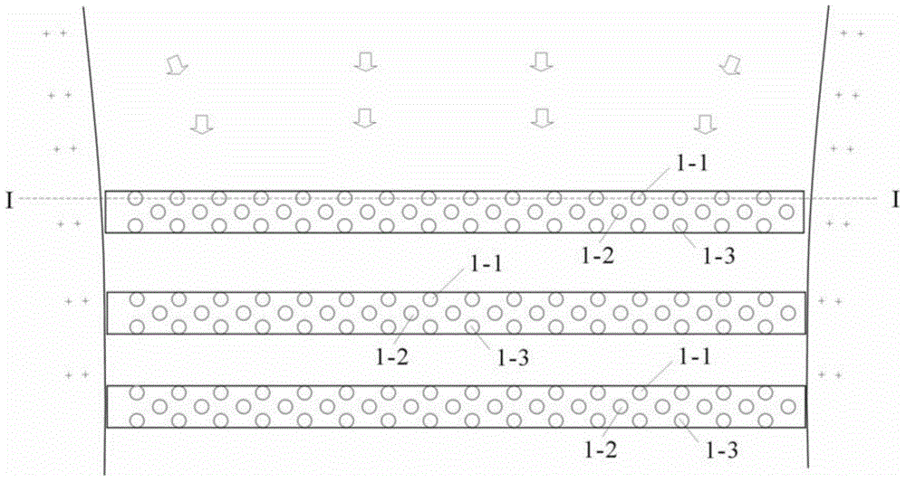
Embodiment 1

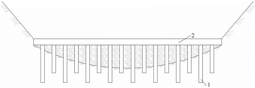
[0026] Example 1: Conditions in the construction area: a large number of geological disasters such as collapses and landslides developed on both sides of the ditch. The total amount of solid material sources is estimated to be less than 4 million cubic meters, and the dynamic reserves are 1.4 million cubic meters. The reserves are 6.8 million square meters. The damming bodies and breaches formed in the debris flow have the characteristics of strong erosion and high mud level. In order to prevent further debris flow outbreaks in the main and branch ditches in this area, more solid matter sources will be rushed out, forming a disaster-causing blocking debris flow, the specific construction steps are as follows. The first step: level measurement and positioning. Level the site, measure and set out the lines according to the pile position, spacing and elevation required by the design and construction; the second step: construct 3 small-diameter pile groups, and the first, second ...

Embodiment 2

[0027] Example 2: Conditions of the construction area: the local terrain of the debris flow ditch is relatively open and gentle, the slope is less than 10°, the water flow is slow, the water volume is small, and the flow rate is 50m 3 / s below. In this case, 2 small-diameter pile groups will be constructed after leveling the site at the mouth of the ditch, and a total of 300 prefabricated small-diameter piles in 2 rows and 3 rows will be laid at the 50m-long ditch. The rows of small-diameter piles are arranged in the shape of "pin". The pile diameter is 200mm, the center distance between two adjacent rows of piles is 200mm, and the center distance between the same row of small-diameter piles is 600mm. The piles of the same row in the first column on the facing surface are of different lengths, and the long and short piles are arranged at intervals in sequence. The long piles are 5m, the short piles are 3m, and the second piles are all 3m short piles. Cast rib beams on site, ...


PUM


Abstract

The invention relates to a small-caliber combined rib bottom pile protection structure for a super-large high-position mud-rock flow, in particular to a small-caliber combined rib bottom pile protection structure in allusion to a blocking collapse effect of the super-large high-position mud-rock flow, belongs to the technical field of geological disaster prevention safety, and is widely applicable to control of the super-large high-position mud-rock flow in a high and steep mountainous region. The small-caliber combined rib bottom pile protection structure comprises multiple small-caliber pile groups and ribbed beams; the multiple small-caliber pile groups comprise more than two small-caliber pile groups; each small-caliber pile group comprises three rows of piles, namely the first row, the second row and the third row; the three rows of piles in each small-caliber pile group are fixedly connected with the top ribbed beams; diameters of the piles in each small-caliber pile group are the same; the first small-caliber pile group is positioned on an impact surface. The small-caliber combined rib bottom pile protection structure quickly enhances the capability of fixing the mud-rock flow source, reduces the rushing-out amount of the mud-rock flow, and reduces the possibility of forming the large-scale high-position high-speed mud-rock flow.

Description

technical field [0001] The invention relates to a mud-rock flow prevention technology, especially a small-caliber combined rib-bottom pile protection adopted for the "clogging effect" of extra-large and high-level debris flows. . Background technique [0002] The extremely large and high-level debris flow is easy to plan and erode due to the inclusion of rocks, scraping the bottom of the ditch and the soil and rocks on both sides of the ditch wall, resulting in dynamic erosion of the ditch bed and side erosion of the ditch wall, forming a "clogging effect" and increasing the flow of debris flow. quantity. Abundant debris flows rushing out of solid materials can easily further cause channel blockage. After the collapse, a blocking debris flow is formed. The flow rate increases several times or even dozens of times, causing the protection project to fail, and seriously threatening the lives and property safety of the majority of residents downstream. In order to prevent debr...

Claims


Application Information

Patent Timeline
Patent Type & Authority Applications(China)
IPC IPC(8): E02D17/20E02D5/30E02D5/34
CPCE02D17/207
Inventor 殷跃平王文沛张楠贺模红闫金凯
Owner 中国地质环境监测院
Learn More