Ionizer unit

An ionizer and discharge electrode technology, applied in electrical components, static electricity, circuits, etc., can solve the problems of ionizer unit installation location limitation, radiation noise, and thickening of power supply lines.

Active Publication Date: 2018-05-11
DAIFUKU CO LTD
View PDF8 Cites 0 Cited by
  • Summary
  • Abstract
  • Description
  • Claims
  • Application Information

AI Technical Summary

Problems solved by technology

Therefore, the power supply line becomes thicker, and the installation position of the ionizer unit may be restricted, or a problem of radiation noise from the power supply line may arise.

Method used


Image

  • Ionizer unit
  • Ionizer unit
  • Ionizer unit

Examples


Embodiment Construction

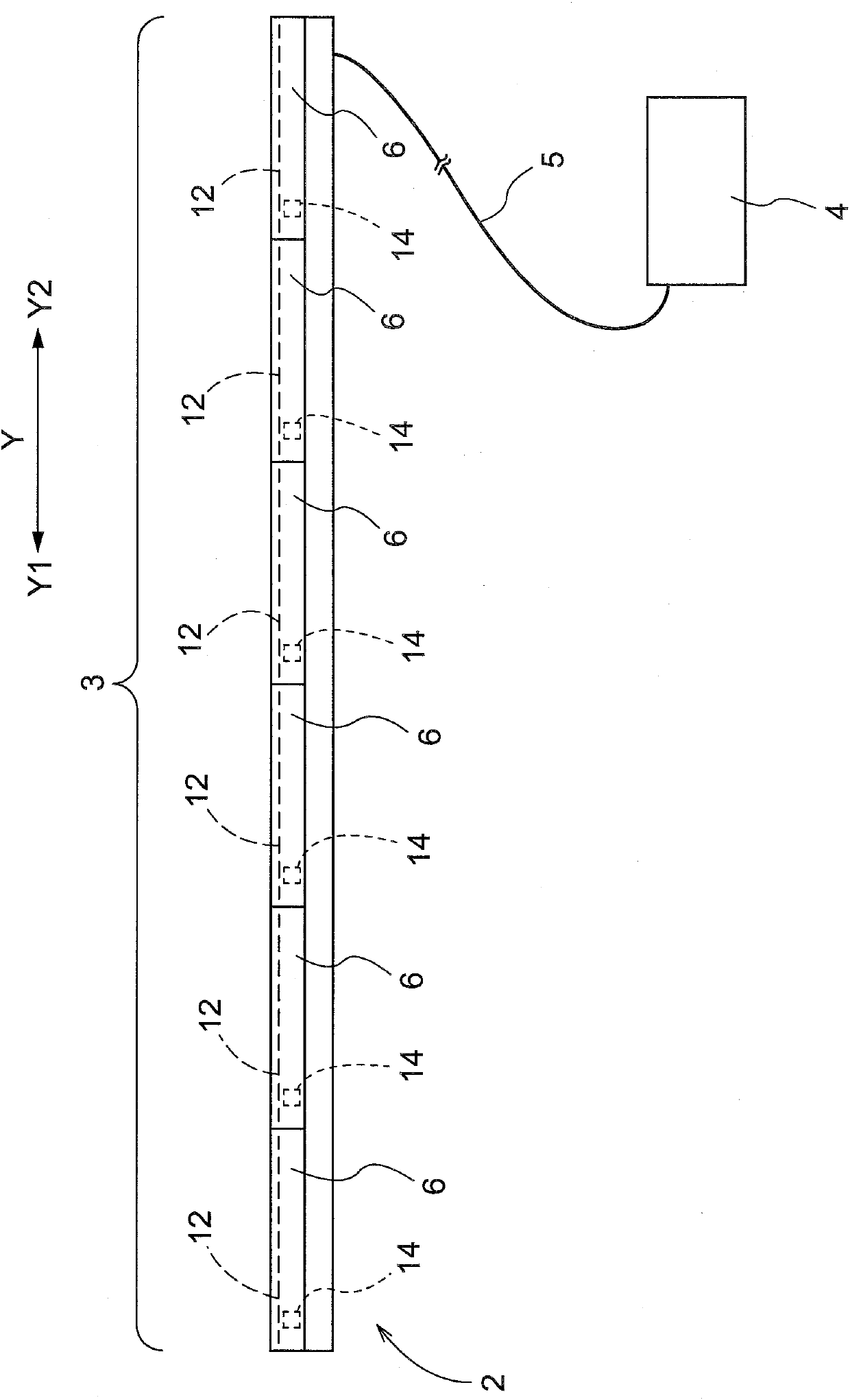
[0014] A first embodiment of the ionizer device will be described based on the drawings. Such as figure 1 as well as figure 2 As shown, the ionizer device 2 is equipped, for example, in the conveyance apparatus 1 which conveys the plate-shaped conveyance W, such as the glass substrate for liquid crystals. The transport device 1 is provided with: a support frame 1W; and a rotating shaft 1J rotatably supported by the support frame 1W. The transport device 1 is equipped with a plurality of rotating shafts 1J arranged in a line in the transport direction C. As shown in FIG. A plurality of conveying rollers 1R are attached to each of the plurality of rotating shafts 1J, and among the plurality of conveying rollers 1R arranged on the rotating shaft 1J, the conveying roller 1R arranged at an end in the longitudinal direction of the rotating shaft 1J is Equipped with large diameter part 1RR. The plurality of rotating shafts 1J are configured to rotate in conjunction with a belt m...


PUM


Abstract

The present invention provides an ionizer unit which is easy to set and is not easy to generate a radiation noise problem. The ionizer unit comprise a rectangular electrode substrate (11), a linear discharge electrode 12 configured on the surface of the electrode substrate 11 and formed into a continuous linear shape along the length direction Y of the electrode substrate (11); a boost transformer(14) electrically connected with the linear discharge electrode 12 and specially arranged relative to the linear discharge electrode 12; and a box body 17 integrally storing the electrode substrate 11 and the boost transformer 14.

Description

technical field [0001] The present invention relates to ionizer units for generating ionized species. Background technique [0002] An example of an ionizer device including an ionizer unit is described in JP-A-9-137634. One ionizer unit having a linear discharge electrode is installed in this ionizer device. In this ionizer unit, since the discharge electrode is configured in a linear shape, ionized species are generated along the linear discharge electrode. Therefore, compared with the case where the ionized species is generated by a locally provided discharge electrode, the ionized species can be uniformly generated in a wide range, and the neutralization target part in the neutralization target object has a constant distribution. It can also play the role of eliminating static electricity without bias. [0003] In such an ionizer unit, generally, a voltage supplied from a power supply is boosted by a step-up transformer, and then supplied to the ionizer unit through a...

Claims


Application Information

Patent Timeline
Patent Type & Authority Applications(China)
IPC IPC(8): H05F3/06
CPCH05F3/06H01T23/00H01T19/04
Inventor 中尾多通夫池田大介
Owner DAIFUKU CO LTD
Why Eureka
Try Eureka