A turbine engine propelled airplane having an acoustic baffle

a turbine engine and airplane technology, applied in the field of airplanes, can solve the problems of limited sound nuisance of the airplane, aerodynamic drag, and boundary layer formation around the fuselage of the airplane, and achieve the effect of limiting the lateral size of the panel and minimizing the propagation of sound waves

Active Publication Date: 2018-12-13
SN DETUDE & DE CONSTR DE MOTEURS DAVIATION S N E C M A
View PDF8 Cites 7 Cited by
  • Summary
  • Abstract
  • Description
  • Claims
  • Application Information

AI Technical Summary

Benefits of technology

[0015]In a plane that is substantially vertical and substantially perpendicular to the longitudinal axis of the turbine engine, the panel preferably extends laterally between two lateral ends, a straight line passing through each lateral end of the panel and the center of the air inlet of the at least one fan of the turbine engine forming an angle with an axis substantially perpendicular to the longitudinal axis of the turbine engine that lies in the range 60° to 90°. Such an angle thus makes it possible to optimize the action of the panel in order to minimize soundwave propagation and satisfy as well as possible the acoustic certification standards relating to laterally radiated noise.
[0016]Under such circumstances, each lateral end of the panel may each be terminated by a respective winglet, the winglets being oriented so as to bring the panel towards the turbine engine. The presence of such winglets thus makes it possible t

Problems solved by technology

The sound nuisance of the airplane is also limited thereby.
Furthermore, in flight, a boundary layer forms around the fuselage of the airplane and generates aerodynamic drag.
Nevertheless, architecture with a turbine engine integrated in th

Method used


Image

  • A turbine engine propelled airplane having an acoustic baffle
  • A turbine engine propelled airplane having an acoustic baffle

Examples


Embodiment Construction

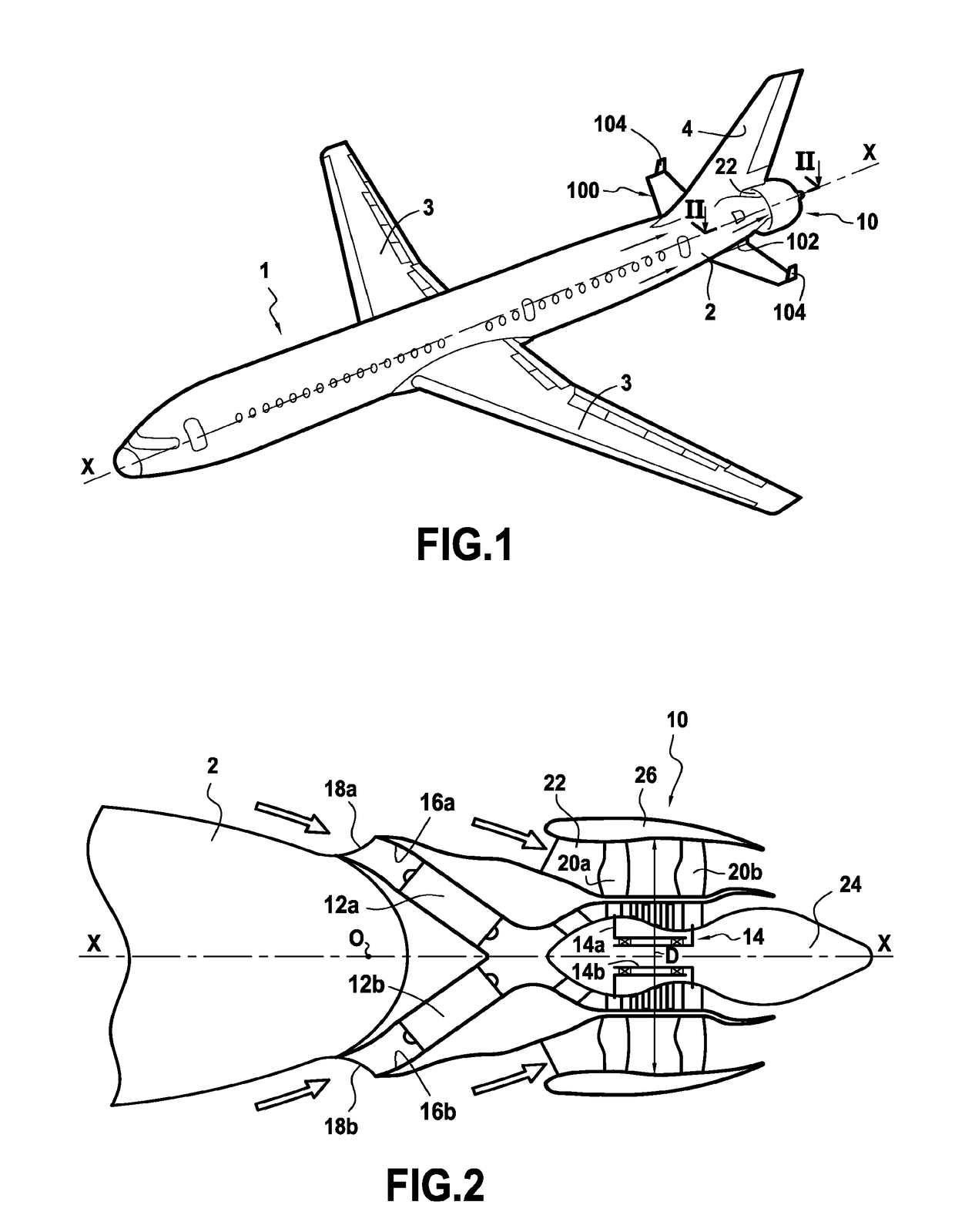
[0023]FIG. 1 shows an airplane 1 in accordance with the invention. This airplane has a turbojet 10 that is integrated in the rear of the fuselage 2 of the airplane and that extends it rearwards.

[0024]FIG. 2 shows an example of an architecture for such a turbojet 10. Reference may be made to Document WO 2014 / 072615, which describes such an architecture in detail, it being understood that the invention is not limited to that type of turbine engine architecture (in particular the number of fans may be other than two, for example there may be only one fan).

[0025]Typically, the turbojet 10 is centered on a longitudinal axis X-X of the fuselage 2 of the airplane and going from upstream to downstream in the gas flow direction it comprises in particular: two distinct gas generators 12a and 12b arranged in parallel and feeding a single working turbine 14. In the description below, the axis X-X is also the longitudinal axis of the turbojet.

[0026]In known manner, each gas generator 12a, 12b co...


PUM


Abstract

An airplane propelled by a turbine engine having at least one fan, the turbine engine being integrated in the rear of a fuselage of the airplane, extending it rearwards, the airplane further including at least one acoustic baffle forming panel connected to the fuselage of the airplane and arranged below the turbine engine.

Description

BACKGROUND OF THE INVENTION[0001]The present invention relates to the general field of airplanes propelled by a bypass turbine engine integrated in part in the fuselage of the airplane.[0002]Civil airplanes are generally fitted with engines mounted under the wings or in a rear position on the fuselage, where they are secured by means of pylons.[0003]Because of the expected increasing cost of fuel in the future, engine manufacturers are seeking to reduce the fuel consumption of civil airplanes. One of the ways that has been envisaged for achieving this is to embed the engines at least in part inside the fuselage of the airplane in order to eliminate the pylons and the fairings of the engines, thereby reducing the weight of the propulsion assembly and reducing its drag. The sound nuisance of the airplane is also limited thereby.[0004]Furthermore, in flight, a boundary layer forms around the fuselage of the airplane and generates aerodynamic drag. Although in the past it used to be con...

Claims


Application Information

Patent Timeline
IPC IPC(8): B64D29/04B64D27/14B64C5/02B64C1/40F02C7/24G10K11/162
CPCB64D29/04B64D27/14B64C5/02B64C1/40F02C7/24G10K11/162F05D2220/323F05D2240/126B64D27/20Y02T50/40B64D27/02
Inventor JODET, NORMAN BRUNO ANDREGONZALEZ, JEREMY PAUL FRANCISCOROLLAND, HERVE
Owner SN DETUDE & DE CONSTR DE MOTEURS DAVIATION S N E C M A
Why Eureka
Try Eureka