
Method for calculating radiation noise generated by pipe wall of water-filling pipeline during reverberation method

A technology for radiating noise and water pipelines, which is used in the measurement of ultrasonic/sonic/infrasonic waves, measuring devices, instruments, etc. It can solve the problems of unnecessary consideration and inappropriate evaluation of radiated noise, and achieve the effect of weakening coupling and reducing sound radiation capability.

Active Publication Date: 2016-06-22
HARBIN ENG UNIV
View PDF7 Cites 9 Cited by
  • Summary
  • Abstract
  • Description
  • Claims
  • Application Information

AI Technical Summary

Problems solved by technology

This patent relates to the air-borne noise generated by exciting the pipe wall when there is water flowing in the drain pipe. Since the test system is a circulating piping system, it does not involve the jet noise generated when the water flows out of the pipe orifice.
[0005] The radiation noise test of drainage pipes in the air does not need to consider the interaction between the air medium and the pipe, that is, the coupling between the pipe and the air medium, but the interaction between the pipe and the water medium must be considered under water, such as the characteristic impedance ratio of the steel pipe The characteristic impedance of water is only 30 times larger, and the characteristic impedance of polyvinyl chloride plastic rigid pipe is only 5 times larger than that of water. Since the acoustic characteristic impedance of air and water media differs by nearly 3500 times, the drainage pipe in the air The test system and test method are not suitable for the evaluation of radiated noise of underwater water-filled pipelines

Method used


Image

  • Method for calculating radiation noise generated by pipe wall of water-filling pipeline during reverberation method
  • Method for calculating radiation noise generated by pipe wall of water-filling pipeline during reverberation method
  • Method for calculating radiation noise generated by pipe wall of water-filling pipeline during reverberation method

Examples


Embodiment Construction

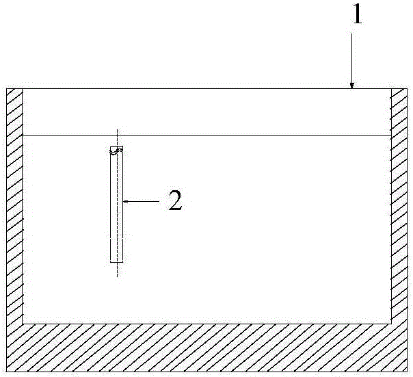
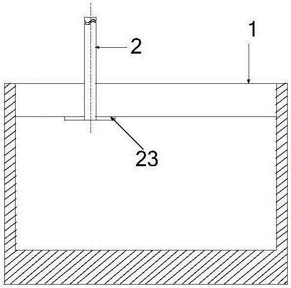
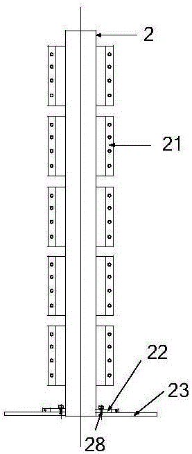
[0034] The following will be combined with figure 1 ~ attached Figure 10 The present invention is described in further detail.

[0035] The purpose of the present invention is to provide a method for calculating the radiation noise generated by the pipe wall of the water-filled pipeline in the reverberation method, which can be used for evaluating the radiation noise of the water-filled pipeline by the pipe wall in the underwater water-filled pipeline radiation noise test carried out by the reverberation method. Radiated noise from vibration provides a calculation method.

[0036] A method for calculating the radiated noise of water-filled pipes produced by the pipe wall in the reverberation method, based on the radiated noise test of water-filled pipes carried out by the reverberation method in a non-anechoic pool, including the water-filled pipes measured by the reverberation method The radiation noise and jet noise generated by the vibration of the pipe wall, the water-f...


PUM


Abstract

The invention discloses a method for calculating the radiation noise generated by the pipe wall of a water-filling pipeline during the reverberation method. According to the method, firstly, the radiation noise and the jet noise, generated due to the vibration of the pipe wall of a water-filling pipeline, are measured based on the reverberation method. Secondly, only the jet noise of the water-filling pipeline is measured and obtained based on the reverberation method, so that the radiation noise of the underwater water-filling pipeline generated during the vibration process is obtained. The above method is simple in calculation and high in efficiency. The radiation noise and the jet noise, generated by the pipe wall of the water-filling pipeline in a single non-noise-elimination pool and measured based on the reverberation method, is subtracted by the jet noise of the water-filling pipeline measured based on the reverberation method. In this way, the radiation noise of the water-filling pipeline generated during the vibration process is obtained.

Description

technical field [0001] The invention belongs to the field of acoustic measurement, in particular to a method for calculating radiation noise generated by a pipe wall in a water-filled pipe in a reverberation method. Background technique [0002] The radiation noise of the underwater water-filled pipeline is composed of two parts: one is that when the water in the water-filled pipeline is flowing, it encounters changes in the shape of the pipeline structure (such as elbows and changes in the cross-sectional area of ​​the pipeline), because the water flow and the shape of the pipeline structure Interaction produces radiation noise; if the absolute roughness of the pipe wall is too large, when the water flows quickly, it will also excite the pipe wall and generate radiation noise; when the water pump as the jet source is also transmitted to the underwater due to its own huge vibration The water-filled pipeline produces radiation noise; this kind of noise is caused by the vibrat...

Claims


Application Information

Patent Timeline
IPC IPC(8): G01H17/00
CPCG01H17/00
Inventor 刘永伟商德江
Owner HARBIN ENG UNIV
Learn More