
Apparatus for ejecting droplets, actuator controller used in the apparatus, and method for controlling the actuator

a technology of actuator controller and droplet, which is applied in the direction of electrical equipment, printed circuits, printing, etc., can solve the problems of deteriorating printing quality and relatively low ejection speed of droplets, and achieve stable ejection of minute droplets and small volume

Active Publication Date: 2007-06-26
BROTHER KOGYO KK
View PDF16 Cites 6 Cited by
  • Summary
  • Abstract
  • Description
  • Claims
  • Application Information

AI Technical Summary

Benefits of technology

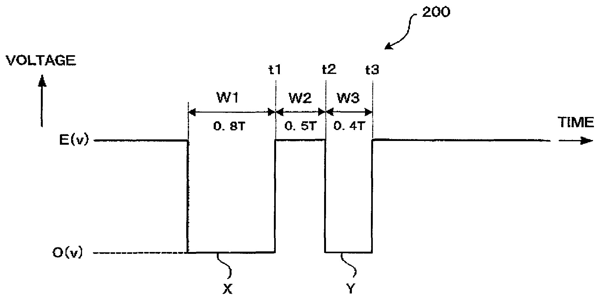
[0011]According to the aforementioned first to third aspects, by setting the pulse width of the ejection pulse signal to be shorter than the time T required for a pressure wave to propagate in one way longitudinally through the liquid containing chamber, a volume of liquid to protrude from the nozzle on completion of the application of the ejection pulse signal can be reduced. Then, the application of the additional pulse signal pulls a part of the liquid protruding from the nozzle back toward the liquid containing chamber, so that a droplet to be actually ejected can have a further smaller volume than the volume of the liquid that has protruded from the nozzle. In this way, the above construction realizes an ejection of a minute droplet while it enables a droplet to be ejected at a relatively high speed, Thus, a stable ejection of minute droplets is realized.

Problems solved by technology

However, when each pulse signal is applied in accordance with the pulse width and the application timing as described above, an ejection speed of a droplet becomes relatively low.
A low ejection speed of a droplet causes an unstable ejection to thereby deteriorate printing quality.

Method used


Image

  • Apparatus for ejecting droplets, actuator controller used in the apparatus, and method for controlling the actuator
  • Apparatus for ejecting droplets, actuator controller used in the apparatus, and method for controlling the actuator
  • Apparatus for ejecting droplets, actuator controller used in the apparatus, and method for controlling the actuator

Examples


Embodiment Construction

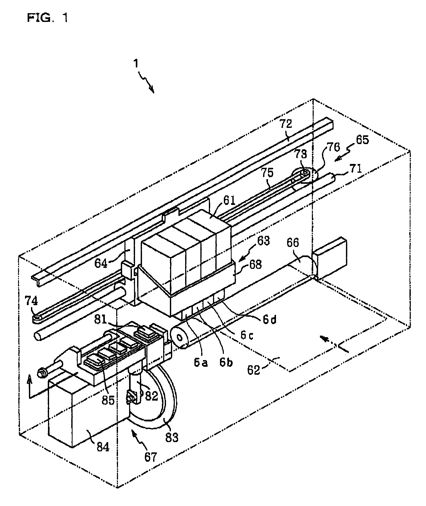
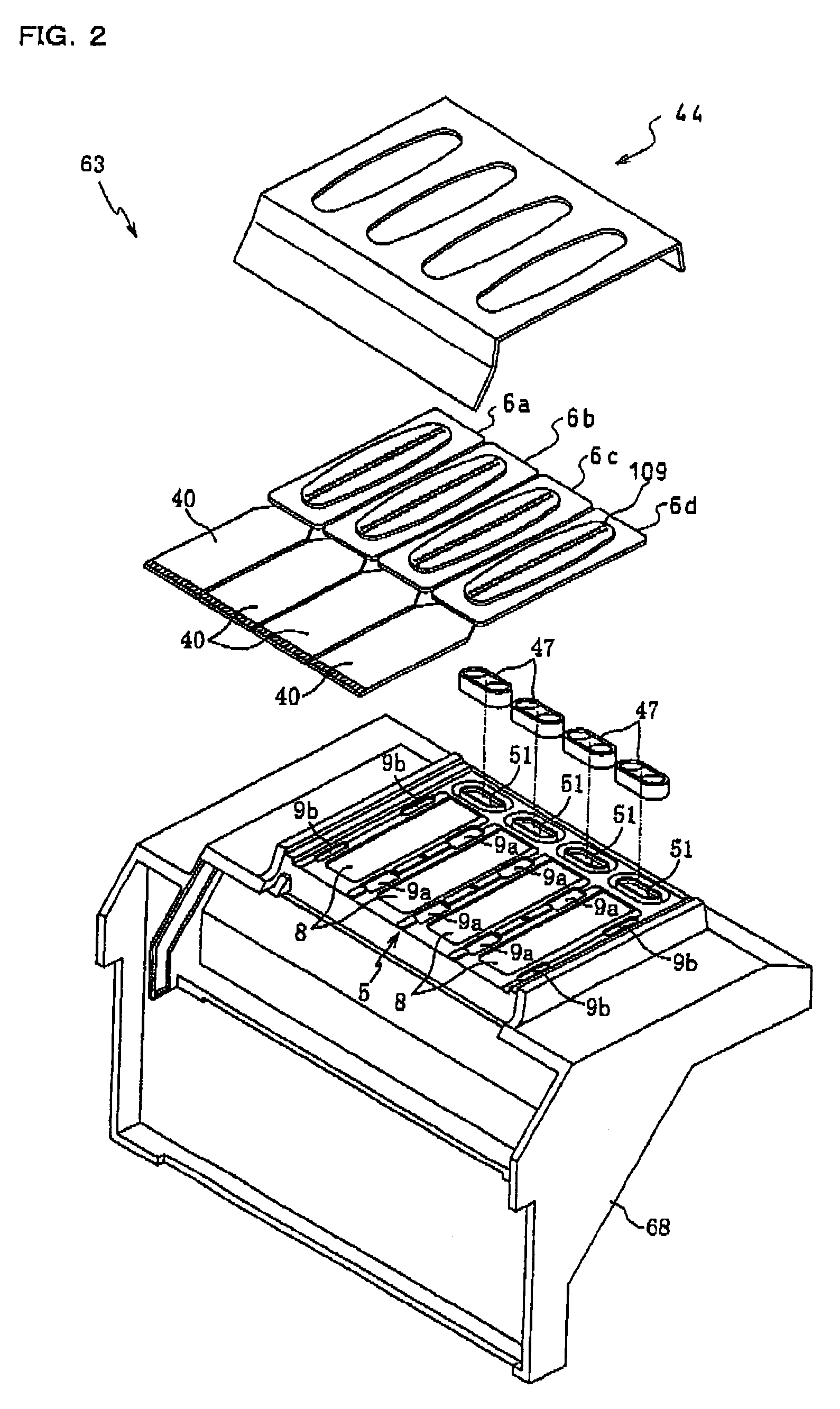
[0022]An internal structure of an ink-jet printer (an apparatus for ejecting droplets) according to an embodiment of the present invention will firstly be described with reference to FIG. 1. A head assembly 63 is arranged within an ink-jet printer 1. Four piezoelectric ink-jet heads 6a, 6b, 6c, and 6d for ejecting ink of yellow, magenta, cyan, and black, respectively, are fixed to a main frame 68 of the head assembly 63. Further, four ink cartridges 61 in total that are filled with the respective color ink are detachably attached to the main frame 68 of the head assembly 63. The main frame 68 of the head assembly 63 is fixed to a carriage 64 linearly reciprocated by a drive mechanism 65. A platen roller 66 for forwarding a paper is arranged with an axis thereof being in parallel with a reciprocating direction of the carriage 64. The platen roller 66 confronts the ink-jet heads 6a to 6d.

[0023]The carriage 64 is slidably supported by a guide shaft 71 and a guide plate 72 both dispose...


PUM


Abstract

In an apparatus for ejecting droplets having nozzles that eject droplets, liquid containing chambers each connected at one longitudinal end thereof with a corresponding nozzle, and an actuator that changes a volume of each of the liquid containing chamber, an ejection pulse signal and an additional pulse signal each increasing the volume of the liquid containing chamber are sequentially applied in accordance with a one-dot printing instruction. When the volume of the liquid containing chamber decreases upon completion of the application of the ejection pulse signal, liquid becomes protruding from the nozzle. The additional pulse signal is then applied to pull a tail portion of the liquid back toward the liquid containing chamber, thereby ejecting a fine droplet. A time interval between a completion of the application of the ejection pulse signal and a start of the application of the additional pulse signal are set at defined times.

Description

BACKGROUND OF THE INVENTION[0001]1. Field of the Invention[0002]The present invention relates to an apparatus for ejecting droplets capable of ejecting minute droplets, an actuator controller used in the apparatus, and a method for controlling the actuator.[0003]2. Description of Related Art[0004]A printing head in an inkjet printer includes therein an ink tank and pressure chambers. Each pressure chamber is supplied with ink from the ink tank. An actuator is arranged to correspond to each pressure chamber. When the actuator is driven to change a volume of a pressure chamber, ink in the pressure chamber is pressurized to be ejected through a nozzle connected with the pressure chamber. Particularly in order to eject minute droplets for high-resolution printing, there is known a technique, as disclosed in U.S. Pat. No. 6,350,003, in which an ejection pulse signal and an additional pulse signal accompanying the ejection pulse signal are sequentially applied to an actuator in accordance...

Claims


Application Information

Patent Timeline
Patent Type & Authority Patents(United States)
IPC IPC(8): B41J29/38B41J2/05B41J2/045B41J2/055H05K3/12
CPCB41J2/04573B41J2/04581B41J2/04588B41J2002/14217B41J2002/14225H05K3/1241
Inventor SEKIGUCHI, YASUHIRO
Owner BROTHER KOGYO KK
Learn More