Candle filter elements and method for fixing same in a pressure vessel

a technology of pressure vessel and clamping element, which is applied in the direction of gravity filter, loose filtering material filter, cartridge filter, etc., can solve the problems of inability to clean properly, inability to sterilize the clamping element internally in place, and inability to use aseptic or steril

Inactive Publication Date: 2002-07-02
DRM DR MULLER
View PDF8 Cites 7 Cited by
  • Summary
  • Abstract
  • Description
  • Claims
  • Application Information

AI Technical Summary

Benefits of technology

As a coupling for filter elements, it is an advantage for the connecting cams to be located on a large diameter so that the lever arm to

Problems solved by technology

The couplings used can only be sterilized internally in place, and cannot be properly clean

Method used


Image

  • Candle filter elements and method for fixing same in a pressure vessel
  • Candle filter elements and method for fixing same in a pressure vessel
  • Candle filter elements and method for fixing same in a pressure vessel

Examples


Embodiment Construction

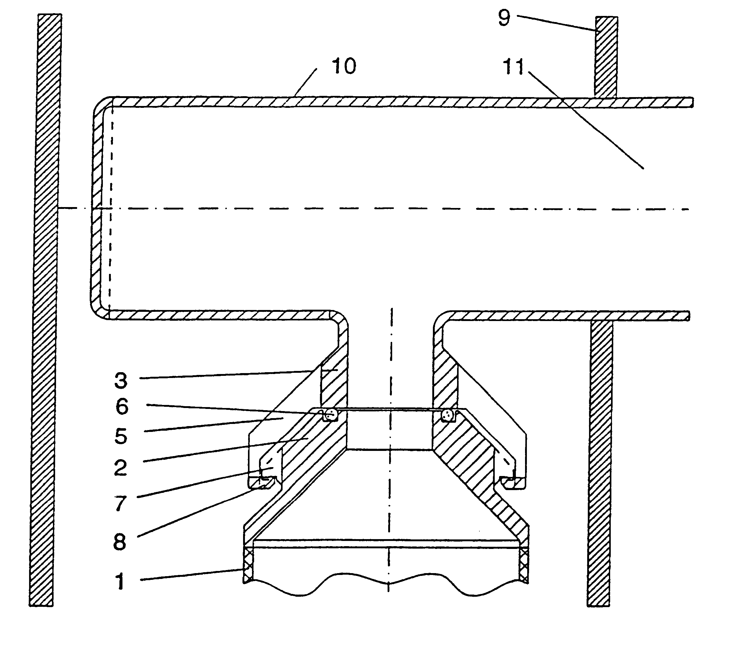
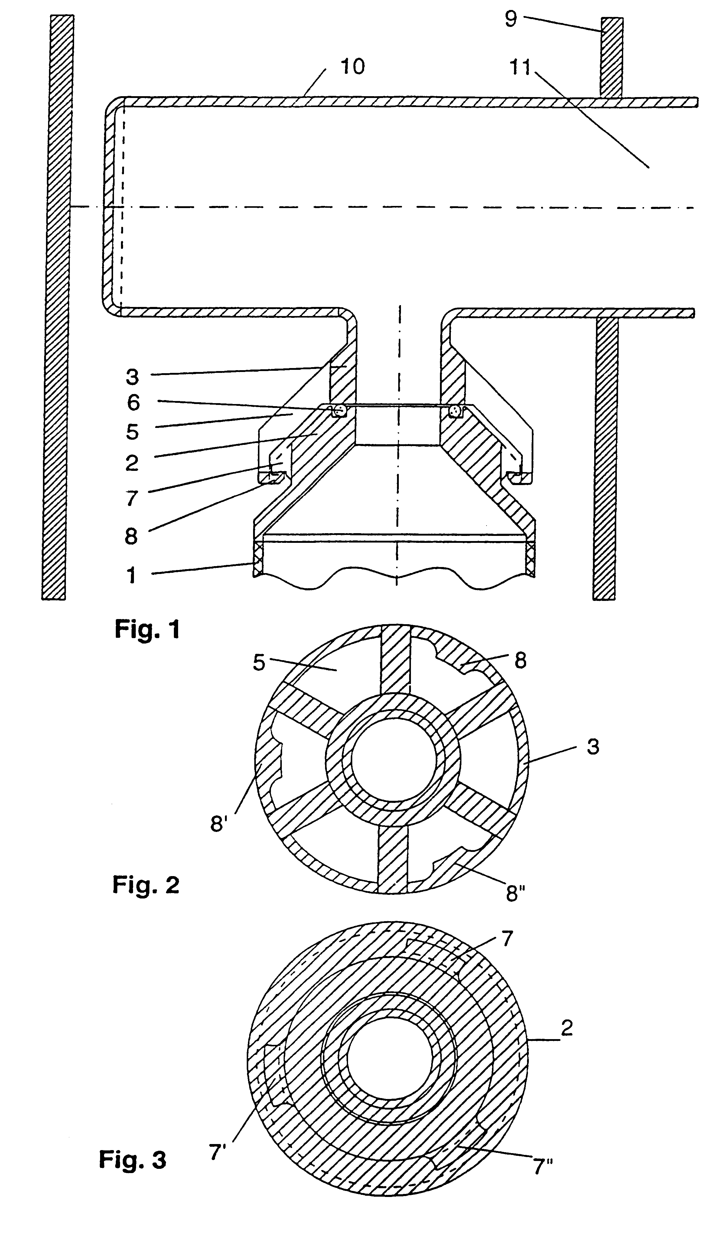
In FIG. 1 the reference number 1 denotes a filter element. The filter element 1 is attached to a lower coupling part 2 in a known manner. The lower coupling part 2 and an upper coupling part 3 form a cavity, designated the dip tube 4. An opening is formed between the coupling part 2 and the coupling part 3 as a rinsing space 5. The coupling part 2 is connected to the coupling part 3 via a seal ring 6. Fastening cams 7, 7', 7" are provided on the coupling part 2, and fastening cams 8, 8', 8" are provided on the coupling part 3. The dip tube 4 communicates with a collector tube 10 with a filtrate outlet 11, mounted in a pressure vessel 9.

In FIG. 2 of the lower coupling part 2 is shown in plan view, with fastening cams 8, 8', 8" and rinse opening 5.

In FIG. 3 the lower coupling part 2 is shown in plan view, with fastening cams 7, 7', 7".

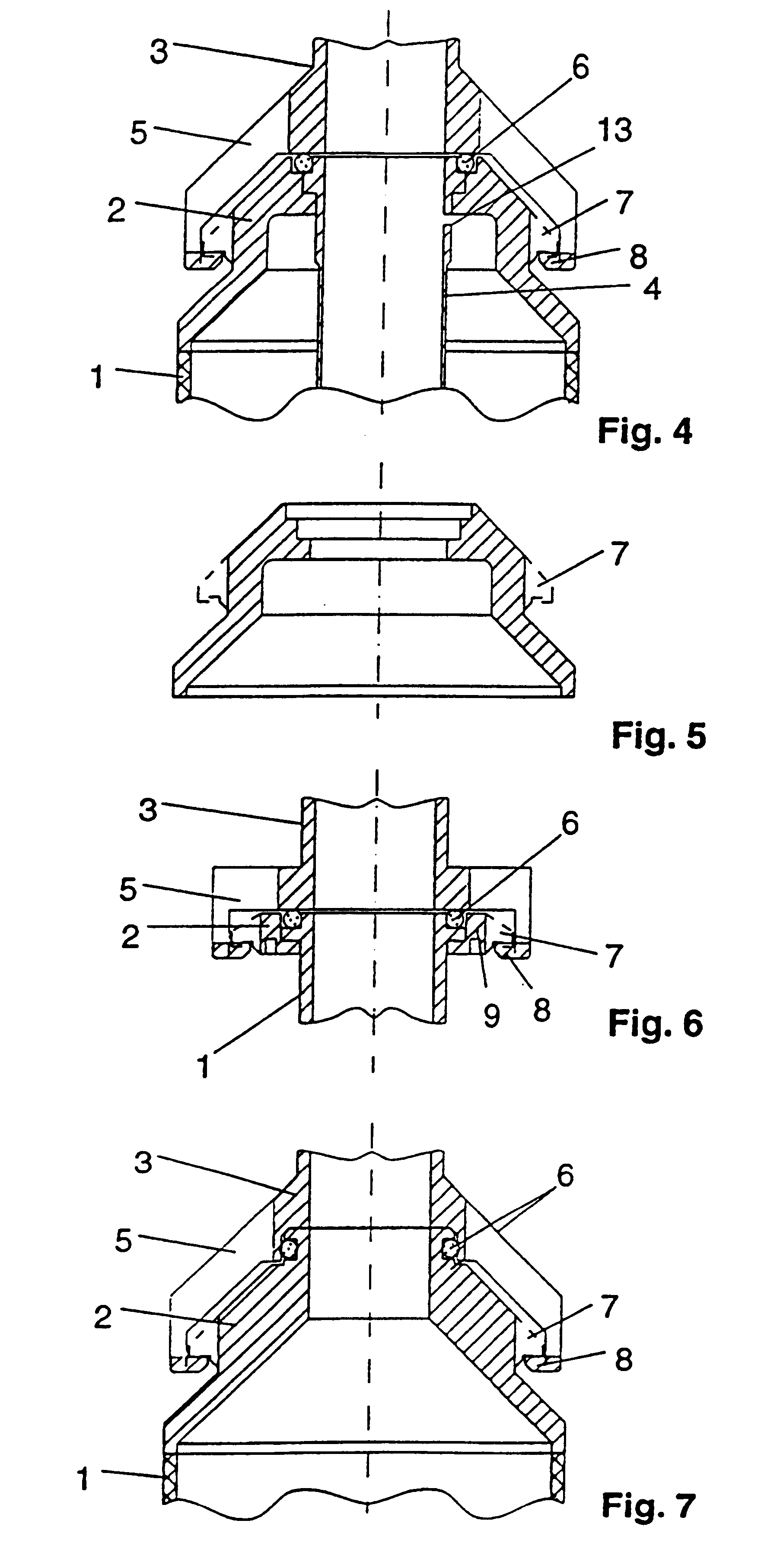
FIG. 4 shows a variant of the fixing according to the invention with an extended dip tube 4 leading into the filter element 1. The dip tube is provided ...


PUM


Abstract

A candle filter element adapted to be located inside a pressure vessel and fixed in a hanging position to a collector tube for aseptic and/or sterile filtration of liquids, has a coupling with conical upper coupling part and a conical lower coupling part, with the conical upper coupling part provided with a rinsing opening and a pair of cams.

Description

BACKGROUND OF THE INVENTIONThe invention relates to candle filter elements which are fixed in a hanging position to a collector tube inside a pressure vessel for the aseptic and / or sterile filtration of liquids, including a coupling with a conical upper coupling part, a conical lower coupling part, and a part of cams.One candle filter element of this type which is suitable for sterile filtration in a pressure vessel is known from WO 94 / 23819. In order to clean the filter elements, one can remove the central tube serving as a support body without having to open the filter container. The couplings used can only be sterilized internally in place, and cannot be properly cleaned without dismantling.Besides screw-type fasteners, quick-acting fasteners are also used for fixing candle filter elements. For instance, CH-A 660850 describes one such quick-acting fastener which is suitable for filtration of radioactive effluents and which enables the filter elements to be exchanged easily by mea...

Claims


Application Information

Patent Timeline
IPC IPC(8): B01D29/11A61L2/06
CPCB01D29/114B01D29/96B01D2201/0469B01D2201/4015
Inventor SCHUMACHER, IVO
Owner DRM DR MULLER
Why Eureka
Try Eureka