Computer processable interconnect topology

a technology of interconnection and topology, applied in the field of computer processable interconnection topology, can solve the problems of increasing the complexity of interconnection and control of devices, and achieve the effect of improving the interconnection and control efficiency of devices

Inactive Publication Date: 2002-08-06
INTEL CORP
View PDF2 Cites 59 Cited by
  • Summary
  • Abstract
  • Description
  • Claims
  • Application Information

AI Technical Summary

Problems solved by technology

Although such devices offer an increased level of performance and functionality, these devices are also becoming more complex to interconnect and control.

Method used

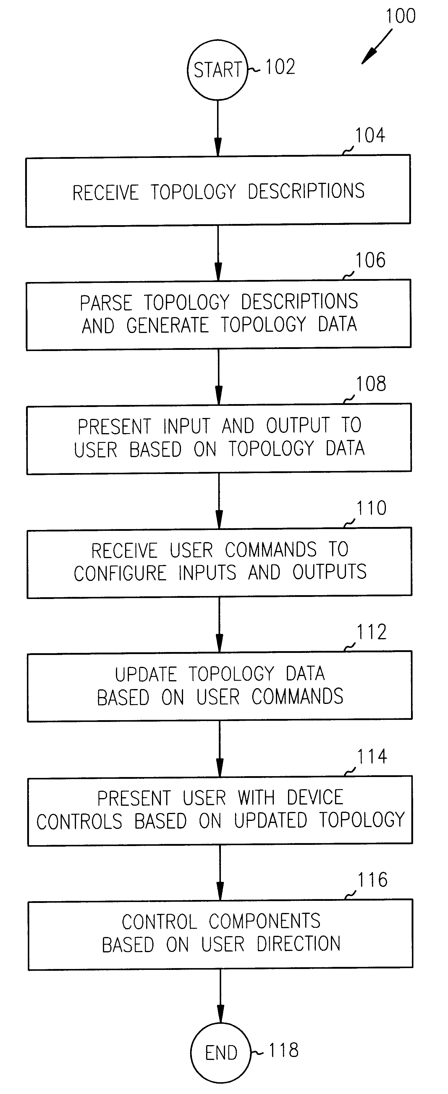
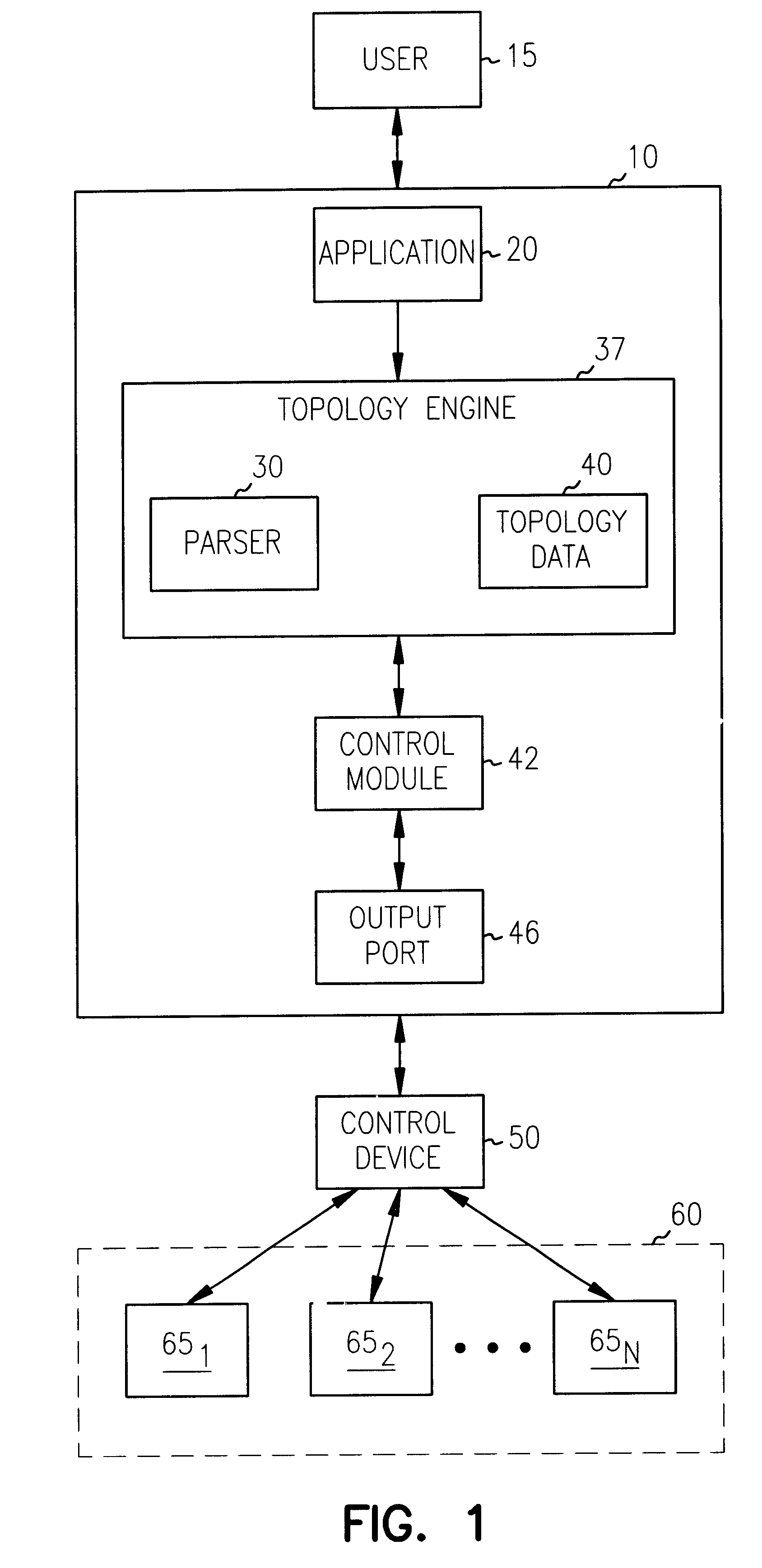
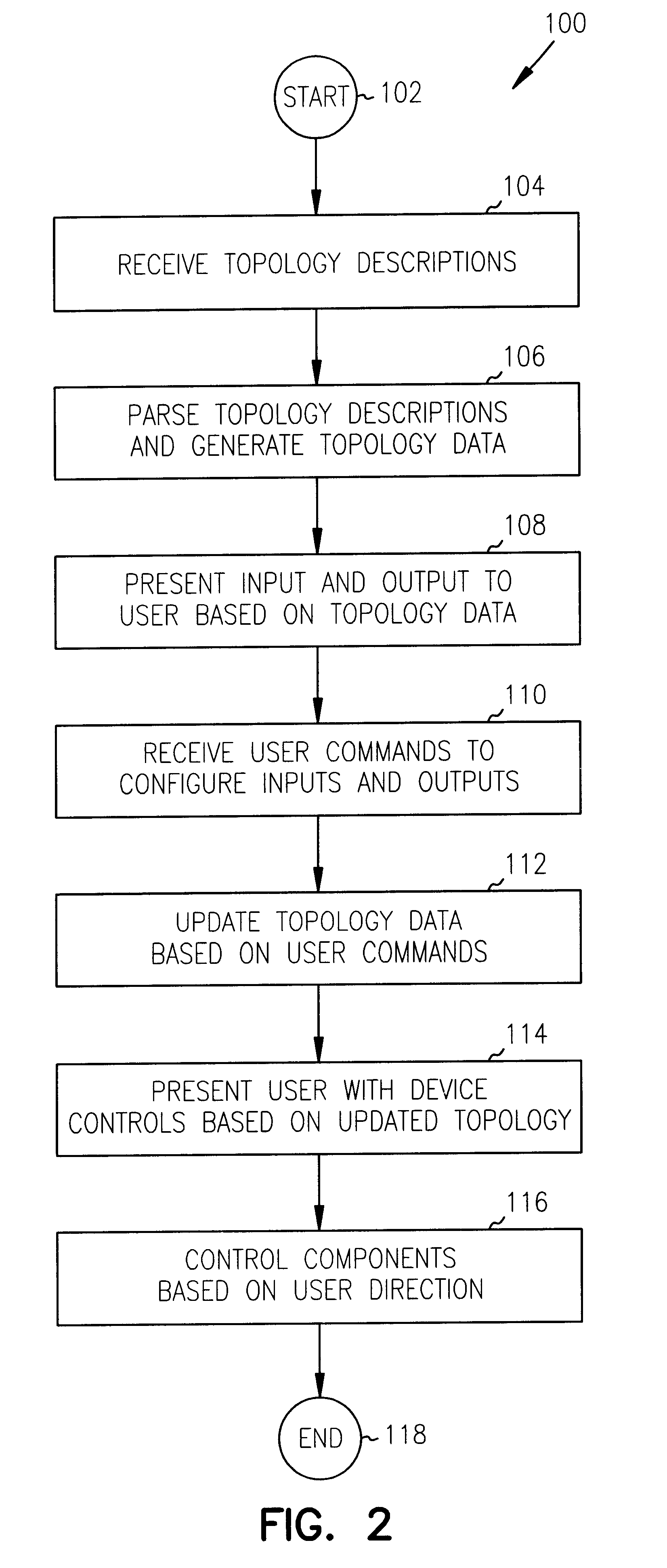

Image

  • Computer processable interconnect topology
  • Computer processable interconnect topology
  • Computer processable interconnect topology

Examples


Embodiment Construction

In order to illustrate the use of the inventive topology description language, a block diagram of an exemplary electronic environment 200 is illustrated in FIG. 3. In this example, electronic environment 200 has seven interconnected electronic components: television 202, video cassette recorder (VCR) 205, audio / video receiver 210, digital video disc player (DVD) 212, speakers 216, headphones 218 and antenna 214. The following listing is one embodiment of a topology description for electronic environment 200:

The above topology description defines an outer block entitled `LabStack` that represents the entire electronic environment 200. Sub-blocks are defined for antenna 214, speakers 216 and headphones 218. Each sub-block defines available inputs and outputs for the corresponding electronic component. An include file is used for each electronic component that requires a more complex description such as television 202, VCR 205, receiver 210 and DVD 212. The above topology description d...


PUM

PropertyMeasurementUnit
mechanicalaaaaaaaaaa
volumeaaaaaaaaaa
frequencyaaaaaaaaaa

Abstract

A computing system for processing a topology description language that describes an electronic environment having one or more electronic components such as a video cassette recorder (VCR), a television, a compact disc player, and an audio / video receiver. The computing system processes the description language in order to display suitable configurations, monitor usage, and even directly control the electronic components. The computing system includes a topology engine that processes the unique topology description language and generates topology data as a function of the topology descriptions. The topology engine provides an application programming interface (API) by which applications, such as a user interface, configure and control the electronic components.

Description

This invention relates generally to configuring and controlling electronic devices and, more particularly, to a method and apparatus for processing a topology language that describes the interconnection of multiple electronic devices.BACKGROUND INFORMATIONElectronic components such as video cassette recorders (VCR), televisions, compact disc players, audio / video receivers, sound processors, etc., are becoming more and more sophisticated. Although such devices offer an increased level of performance and functionality, these devices are also becoming more complex to interconnect and control. Therefore, for these reasons and for other reasons stated below which will become apparent to those skilled in the art upon reading and understanding the present specification, there is a need in the art for a language that facilitates the description of electronic components. There is a need for a computing system capable of processing the language in order to recommend suitable configurations fo...

Claims


Application Information

Patent Timeline
Patent Type & Authority Patents(United States)
IPC IPC(8): G06F17/50H04N5/44H04N5/765G11B31/00H04N5/45H04N5/775
CPCG06F17/50H04N5/44H04N5/765G06F2217/74G11B31/00H04N5/45H04N5/775H04N5/7755H04N21/4316H04N21/435H04N21/4431H04N21/485G06F2111/12G06F30/00H04N21/4112
Inventor TOLL, KIM R.
Owner INTEL CORP
Why Eureka
Try Eureka