Rotating catch lock, specially for motor vehicles

a technology for motor vehicles and latches, applied in the field of rotating latches, can solve the problems of occupants trapped in the vehicle, more energy is required, and a large amount of power is required to operate the motor,

Inactive Publication Date: 2002-08-20
HUF HULSBECK & FURST GMBH & CO KG
View PDF18 Cites 80 Cited by
  • Summary
  • Abstract
  • Description
  • Claims
  • Application Information

AI Technical Summary

Benefits of technology

First, the invention shifts the loading of the energy storage mechanism by the motor into a time phase different from the reversing movement by which the latch leaves its blocking position and returns to its release position with respect to the rotary catch. The latch is returned while the motor is operating in the forward direction, whereas the energy storage mechanism is now loaded while the motor is operating in reverse. The energies required for these two measures are therefore not additive but separate, and this makes it possible to use low-power motors. Such motors are inexpensive and space-saving.

Problems solved by technology

The disadvantage of the known rotary catch lock is the relatively large amount of power required to operate the motor.
When the known rotary catch lock is used in a motor vehicle and the vehicle is involved in a crash, the various components of the lock are deformed, and thus more energy is required to move the latch from the locking position to the release position; if the motor is not powerful enough, it will be unable to operate the rotary catch lock, and the occupants will be trapped in the vehicle.
The known rotary catch locks require powerful motors, which are not only expensive but also very bulky.
This is a problem because of the limited amount of room available in the area of a rotary catch lock.

Method used


Image

  • Rotating catch lock, specially for motor vehicles
  • Rotating catch lock, specially for motor vehicles
  • Rotating catch lock, specially for motor vehicles

Examples


Embodiment Construction

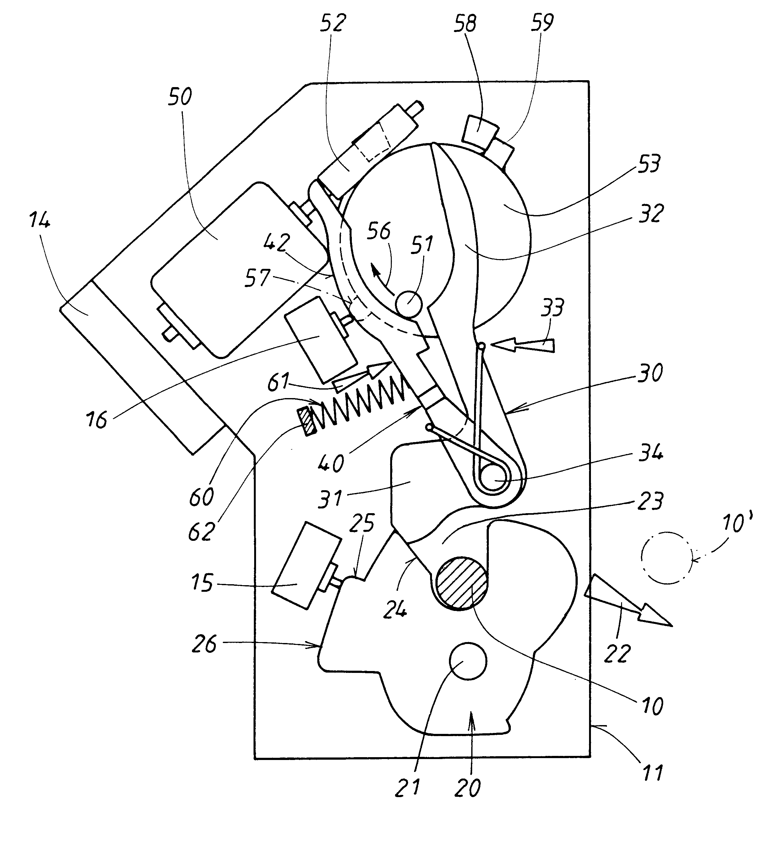
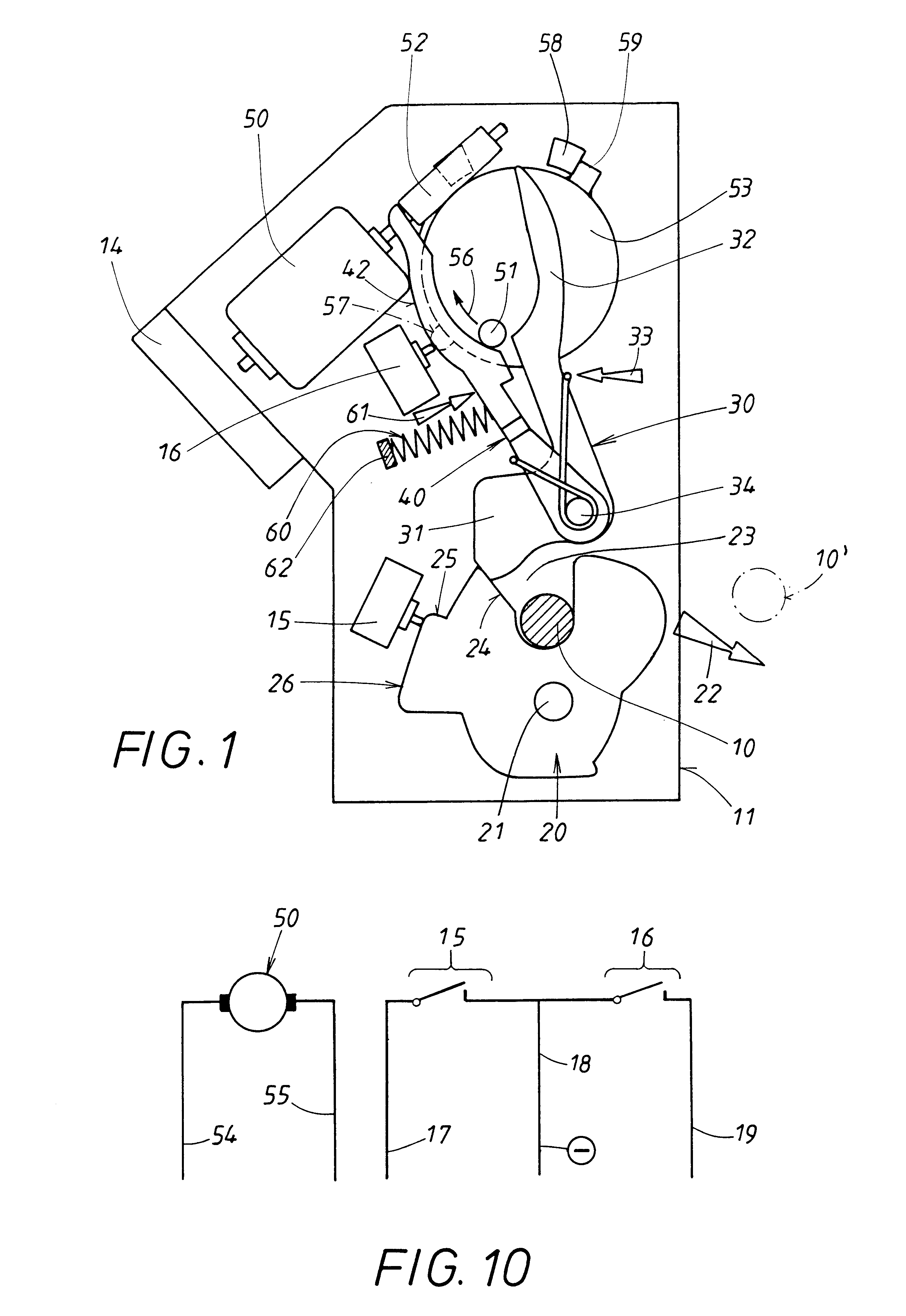
The rotary catch lock comprises a closing element 10, designed here as a bolt, which is attached permanently to a stationary door post of a motor vehicle body and which is emphasized by shading in the figures for the sake of clarity. The other components of the rotary catch lock are installed in a housing 11 of a movable motor vehicle door, to which a rotary catch 20 in particular belongs. Rotary catch 20 can be rotated between two end positions, one of which is shown in FIG. 1, the other in FIG. 6. In between these two end positions there are several other important intermediate positions, which are shown in FIGS. 2-4. The rotary catch is seated on an axle 21 and is subject to a restoring force acting upon it, which can arise in various ways and which is illustrated by a force arrow 22 in the figures. Restoring force 22 tries to rotate rotary catch 20 into the rotational end position shown in FIG. 6, where it is held in a defined position by a stop 12.

The rotary catch has a shaped ...


PUM


Abstract

The invention relates to a rotating catch lock, wherein a closing member (10) interacts with a catch (20), which can be rotated between a closing position accommodating the closing member (10) and an open position which releases said member. The catch (20) is force-loaded (22) in an open position and is held by a spring-loaded (33) rotating latch (30) in the close position. Said latch (30) is moved by a motor (50) between the locking position retaining the catch (20) and a stand-by release position in which the spring-loaded latch (30) is propped up by the catch (20) as long as it remains in an open position. In order to use small compact motors (50), the invention provides that the stored energy (61) exerted by an energy storage mechanism (60) is transmitted to the latch (30) via a storage lever (40). Normally, the latch (30) is shifted into its stand-by position by the storage lever (40). When the latch (30) is in a stand-by position, the storage lever (40) is supported on a control tappet (51) which is rotationally driven by the motor (50). The motor (50) can be driven by an electrical control logic in both a forward mode (56) unloading the energy storage (60) and a reverse mode (56') loading the energy storage (60), i.e. in opposite directions. In the reverse mode (56') the control tappet (51) releases the latch (30), moves towards the storage lever (40) and guides it back into a starting position which corresponds to the stand-by position of the latch (30).

Description

1. Field of the InventionThe invention pertains to a rotary catch lock of the general type indicated in the following. After being rotated into its end position, that is, its closed position, the rotary catch accepts a closing element; this closed position is maintained by a spring-loaded, pivoting latch. In this situation, the latch is in its locking position. When the latch is moved into a release position to release the rotary catch, the rotary catch can then be moved by a restoring force back into its other rotational end position, namely, the open position, where it releases the closing element. As the catch moves into this open position, the spring-loaded latch is moved into a stand-by position, in which it rests against the open rotary catch. The latch is thus ready to move back into its locking position or pre-catch position with respect to the rotary catch when the rotary catch is rotated back into its closed position or into a previous pre-catch position. A motor and an en...

Claims


Application Information

Patent Timeline
Patent Type & Authority Patents(United States)
IPC IPC(8): E05B65/12E05B15/04E05B15/00B60J5/00E05B47/00E05B81/14
CPCE05B81/14E05B2015/0448Y10S292/23Y10T292/1082Y10T70/65Y10T70/7051Y10T70/7062Y10T292/1047E05B81/30E05B81/86E05B47/00
Inventor SZABLEWSKI, PIOTR
Owner HUF HULSBECK & FURST GMBH & CO KG
Why Eureka
Try Eureka